
In this tutorial, We will learn how to control and Configure the 8051/8052 Timers using embedded C. We will learn about the various operating modes of the 8051 Timer like Mode 0, Mode1, Mode 2 etc and how to configure the 8051 timer to use these specific modes.
We will learn to setup timer interrupts of the 8051/8052 to capture Timer overflow events and trigger specific actions based on those events. We will be using both Keil uVision and SDCC (Small Device C Compiler) to Compile our code.
Here we will discuss both the timers of 8051 and 8052 together as the W78E052DDG is an 8052 variant which has an additional timer called T2

Here we will be using the 8051/8052 variant W78E052DDG from Nuvoton for our Experiments. We have an 8051 development board with ADC,7Segment Display, High Current Drivers here for you to try it out .
If you are using a bare 8051 microcontroller, you can use this tutorial to Program the 8051 (W78E052DDG) microcontroller via Virtual COM Port.
Contents
- Source Codes
- Timers of the 8051/8052 MicroController
- Modes of 8051 Timers
- 8051 Timer Special Function Registers(SFR)
- Block Diagram of 8051 Timer Module
- Calculating the Timer Register Value for 8051 Timer
- Configuring the Timer (Start/Stop/Check Flags) in Embedded C
- C code for Configuring Timer 0 in Mode 1
- Starting and Stopping the 8051 Timer
- Generate a 1 Second delay using 8051 timer
- 8051 Code for Generating 1 second delay
- Configuring the Timer Interrupts of 8051
Source Codes

All the C Source Codes along with Kiel Project Files for Configuring and Programming the Timers of 8051 (AT89S51,AT89S52,W78E052DDG,8052) are available from our GitHub Repository.
Download the 8051 Timer Programming tutorial for Beginners as a Zip File.
Browse the 8051 Timer Programming Tutorial on GitHub
Use the Full code from Github Repo. Codes on Website may only show specific parts for brevity.
Datasheets of various 8051 variants are also available on GitHub

Codes are compiled using Keil uVision 5 and SDCC (Small Device C Compiler)
Timers of the 8051/8052 MicroController
The 8051 microcontroller features two independent 16-bit timers, Timer 0 and Timer 1 while the 8052 (W78E052DDG) microcontroller has an additional 16 bit timer called Timer 2.
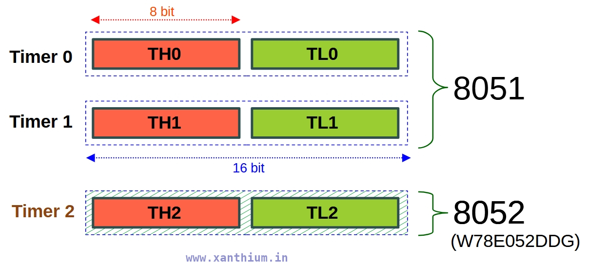
The 16 bit registers are split into two 8 bit Registers called THx and TLx.
For eg for Timer 0 ,TH0 and TL0
For eg for Timer 1 ,TH2 and TL2
The Timers (T0,T1,T2) can be used for two primary functions:
Timer Mode -> To generate precise time delays by counting internal machine cycles.
Counter Mode-> To count external pulses applied to the T0 (P3.4) or T1 (P3.5) pins in 8051 and T2 (P1.0) in 8052 variants
Here We will be dealing with the Timer Mode of 8051 only and Counter Mode will be covered in another article.
Modes of 8051 Timers
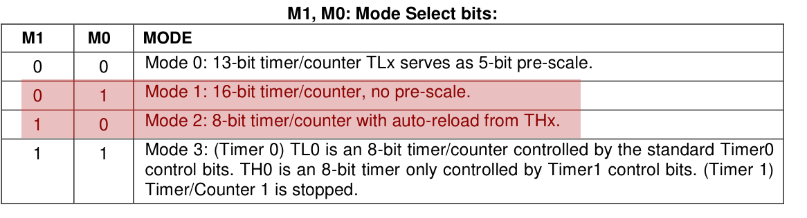
The 8051 Timers can operate in 4 distinct modes named as Mode 0, Mode 1,Mode 2 and Mode 3.Here is a Brief description of the various modes of 8051,its features and uses in embedded programming.
Mode 0
A legacy mode from older processors here the Timer acts as 13-bit Timer.This mode is rarely used.
Mode 1
16-bit Timer Mode. This is the most commonly used mode. Uses both THx (8bit) and TLx (8bit) to count from 0 to 65,535 (16 bit).
Mode 2
8-bit Auto Reload Mode. Here TLx acts as the timer, while THx holds a reload value. When TLx overflows, it automatically reloads the value from THx. This mode is used for baud rate generation by 8051 UART for serial communication.
Mode 3
Split Timer Mode. Splits Timer 0 into two independent 8-bit timers. Timer 1 is usually disabled or used for baud rate generation in this mode. The point of this mode is to provide an extra timer resource when your application is running out of them.
8051 Timer Special Function Registers (SFR)
Now we will discuss about the major Registers ( SFR's) like TMOD,TCON etc and the bits involved in configuring the Timers of 8051 in various modes here.
Timer Registers
These are 16 bit registers that hold the 16 bit value used for counting the time delay.
The 16 bit registers are divided into two 8 bit registers THx and TLx since 8051 is an 8 bit register. For Timer 0 ,it will be TH0 and TL0.
The registers count up from the value loaded into the register till they overflow or reach 0xFFFF.
This specific transition from All 1s to All 0s is what triggers the hardware to set the Timer Flag (TF0 or TF1) to 1.
The timer counters are strictly up counters. The clock for incrementing them are derived from the external oscillator and is divided by 12.
Timer Control SFR (TCON)
The Timer Control (TCON SFR) is a 8 bit Register used to control the operation of Timer 0 and Timer 1 of the 8051 Microcontroller.
The TCON register contains bits that are used to Start the Timer ,Over Flow Flags that are set when the Timer Register overflows and Interrupt edge control.
Please note that Timer 2 in 8052 microcontroller is controlled by a separate register called TCON2 which has different bit fields
Detailed description of the TCON SFR bits can be found below. I will be using TFx or TRx to describe bits of both Timer 0 and Timer 1.If you want to control Timer 0 use TR0 and TF0 and vice versa.
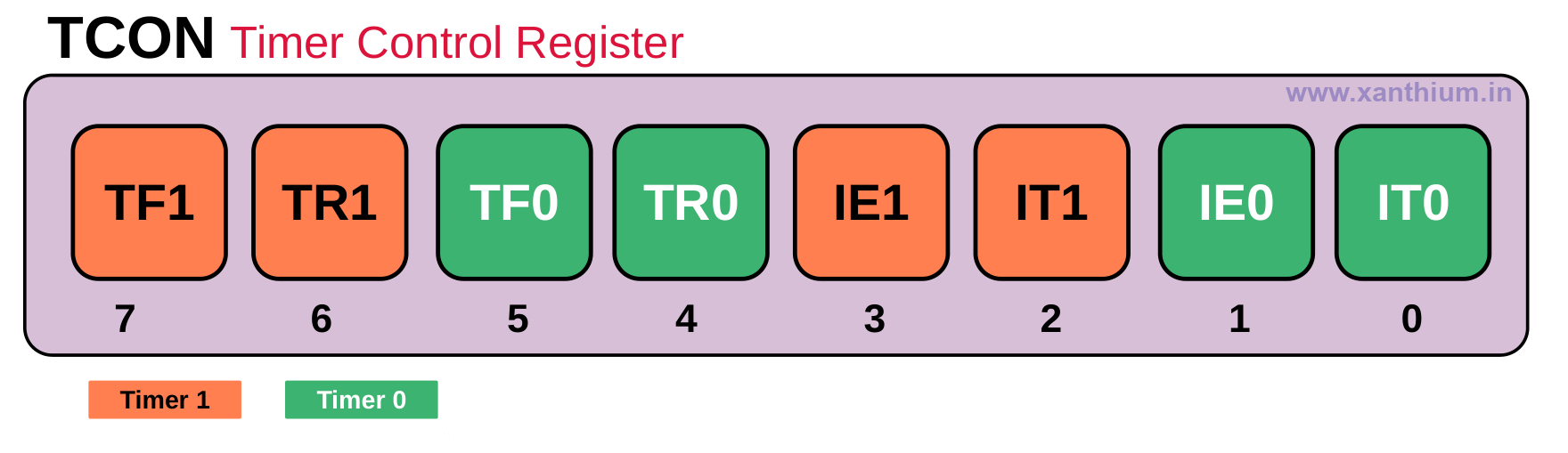
TFx Bit ,Timer Overflow Flag (TF0 for Timer 0 and TF1 for Timer 1 )
- .This bit is set when the 16 bit Timer overflows. It is cleared automatically when the program does a timer interrupt service routine. Software can also set or clear this bit.
- TRx Bit, Timer Run Control Bit (TR0 for Timer 0 and TR1 for Timer 1 )
- Setting this bit will start the counter to start counting up and clearing the bit will stop the counter.
- IE0,IE1,IT0,IT1 are used for controlling the INT0 and INT1 External Interrupt Pins and are not related to any Timer Functions So you can safely ignore them.
Timer Mode Control SFR (TMOD)
This register is used to select between different modes of the Timer Block. TMOD bits can be used to configure the Timer as a Counter or Delay Timer and also to select the different running modes of the Timer like Mode 0,Mode1,Mode 2,Mode 3,Mode 4.
Detailed description of the TMOD SFR bits can be found below.
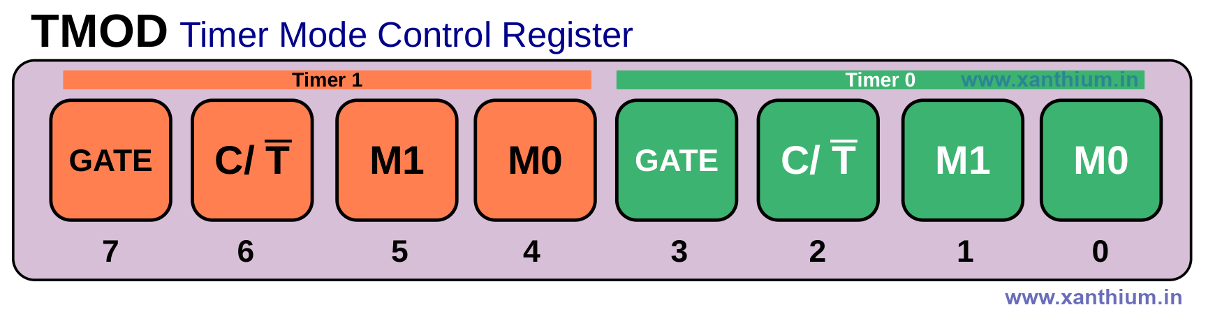
GATE Bit
The Gate Bit in TMOD register is used to control the way the timer is started and stopped.
By default Gate Bit = 0,which means that the Timer is started purely under Software control, If you Set the TRx bit =1 (Eg TR0 =1) ,the timer will immediately start
When Gate Bit =1,the timer will only Start if TRx =1 and the external interrupt pin INTx is High (INT0 or INT1).For Example ,Timer 0 Start only if TR0 =1 and INT0 =1
Can be used for Measuring Pulse Widths
C/T Bit
C/T bit is used to select between Counter and Timer Mode
C/T =0 ,Timer Mode
C/T = 1 Counter Mode
Mode Bits M0,M1
Mode bits are used for selecting the 4 modes of the Timer ,2 Bits M0 and M1 to select the 4 modes of the Timer
Block Diagram of 8051 Timer in Mode 1
The Below image shows a simplified block diagram of the 8051 Timer (Timer 0 or Timer 1).

Here we are using an External Crystal Oscillator of Frequency 11.0592MHz connected to the XTAL1 and XTAL2 pins of 8051 (W78E052DDG).
The 11.0592MHz Clock is divided by 12 internally by the 8051 MCU resulting in an internal clock of 0.9216 MHz which is fed to the Timer register.
The C/T bit decides whether the Timer operates in counter or Timer Mode .Here we are using the Timer mode.
The 16 bit timer Register will increment every 1.085uS .(T = 1/0.9216 MHz ).
Once the Timer reaches FFFFh ,it rolls over and sets the TFx Flag.It will also generate an interrupt if the interrupt option is enabled.
How to Calculate the Timer Register Value for 8051 Timer
Here we will learn how to calculate the timer count that should be loaded into the 16 bit timer register of the 8051 for a specific delay while operating in Mode 1.
First thing to note is the frequency of the external crystal connected to your 8051 MCU's XTAL Pins. In our 8051 development board the frequency of the external crystal is 11.0592MHz.
The External Crystal Frequency is divided by 12 internally, so our effective clock will be External Crystal Frequency /12
The below image shows how the Timers of 8051 receives the clock from the external quartz crystal and how it is pre scaled.
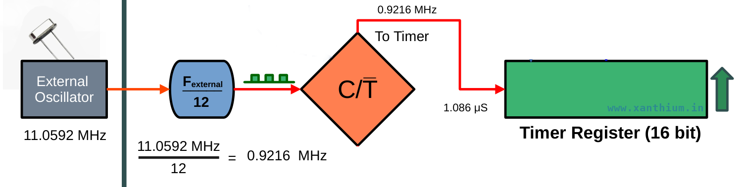
In our case it will be 11.0592MHz/12 = 0.9216 MHz
- If you are using another external crystal ,like 12MHz ,It will be 12MHz/12 = 1 MHz
- If you are using another external crystal ,like 16MHz ,It will be 16MHz/12 = 1.3 MHz
This clock will be fed into the timer and is used to increment the Timer register.
So the Time Period or Ticks = 1/(0.9216 MHz) = 1.085uS (Micro Seconds)
Which means that the timer will increment every 1.085 uS until it reaches the maximum value that is 65,535 and then it will overflow.
So if i load 0 to the Timer register it will take
1.085 uS (Micro Seconds) X 65,536 = 71,172 uS (Micro Seconds)
or 71.17 mS (milli seconds)
for the timer to over flow.
This is the maximum time delay that can be produced by the 16 bit timer for 11.0592 MHz crystal.
Now we need to find the total number of Ticks needed = Desired Time delay /Time of 1 Tick
Lets assume desired Time delay is 10ms (milli second) ,then
total number of Ticks needed =10,000us/1.085us = 9216 ticks
To get a specific delay, you subtract the required ticks from the maximum capacity of the timer
So 65536 - 9216 = 56320
Now Convert 56320 decimal to Hex and load it into the Timer Register
Hex value will be 0xDC00
Now if you are using Timer 0
TH0 = 0xDC; // load high byte
TL0 = 0x00  // load low byte
How to Configure the Timer in Embedded C
In this section, we will learn how to Configure Timer 0 0f 8051 using Embedded C to generate a time delay of 71.1 milliseconds.
We will learn to Start ,Stop and check the Status of Timer 0 over flow Flag (TF0) using a Simple Embedded C Program.
You can find the complete program below. The code is compiled using Keil uVision or SDCC.
//(c) 2026 www.xanthium.in
// Timer 0 is Configured to Generate time delay of 71.1 ms once

// External Crytal Clock = 11.0592 Mhz

// Internal Timer Clock  = External Crytal Clock/12 -> 11.0592 Mhz/12
// Internal Timer Clock  =  0.9216 Mhz
// Ticks (Time Period )  = 1/(0.9216 Mhz)
//                       = 1.085uS (micro seconds)

// 16 bit Timer Counter increments every 1.085uS (micro seconds)
//Compiler used is Kiel uVision 5

//#include <8052.h> use this header file for SDCC instead of reg52.h

#include <reg51.h>   //Header file used by Kiel uVision
void main(void)
{

    TMOD = 0x01;       // Timer0, Mode 1(16-bit)
                       // C/T = 0, So Timer Mode

                       // TMOD Register
                       // [G C/T M1 M0] [G C/T M1 M0]
                       // [0 0   0  0 ] [0 0   0  1 ]

    // Delay = 71.1 mS (milli seconds)

    // Load 0x0000 into the 16 bit Register
    // Timer Counts from 0x0000 -> 0xFFFF or from 0 -> 65,535 ,

    // total steps = 65,536
    // Time Delay = 1.085uS X 65,536 = 71,172 uS (Micro Seconds)
    // or 71.1 mS (milli seconds)

    TH0 = 0x00;        // Load high byte
    TL0 = 0x00;        // Load low byte

    TR0 = 1;           // Start Timer0

    while(TF0 == 0); //if   TF0 = 0 stay here
                     //when TF0 = 1 Exit while loop

    TF0 = 0;      // Manually Clear the Timer overflow Flag
    TR0 = 0;      // Stop the Timer

    while(1); //Stop here.
}
For compiling with SDCC (Small device C Compiler ) replace the header files.
//SDCC Compilation

#include <8052.h> //use this one instead of reg52.h
void main(void)
{
    //Timer 0 Config Code here
}
First we configure the TMOD register to use the Timer 0 .The configuration bytes of Timer 0 are situated at the lower Nibble of TMOD register.
 // TMOD Register
 // [  Timer 1  ] [  Timer 0  ]
 // [G C/T M1 M0] [G C/T M1 M0]
 // [0 0   0  0 ] [0 0   0  1 ]

TMOD = 0x01;  // Timer0, Mode 1(16-bit)
              // C/T = 0, So Timer Mode
So we load 0x01 or Binary 0000 0001 to the TMOD register.
Which sets the Timer 0 in Timer Mode and Mode 1 which is the 16 bit up counter mode.
We load 0x0000 to the Counter register.
TH0 = 0x00; // Load high byte
TL0 = 0x00; // Load low byte
Now the counter will count up from 0 to 65535 (65536 counts)
Here we are using 11.0592MHz External crystal that means each tick of the clock is 1.085 microseconds as shown in the below calculation.
// External Crytal Clock = 11.0592 Mhz

// Internal Timer Clock  = External Crytal Clock/12 -> 11.0592 Mhz/12
// Internal Timer Clock  =  0.9216 Mhz
// Ticks (Time Period )  = 1/(0.9216 Mhz)
//                       = 1.085uS (micro seconds)

// 16 bit Timer Counter increments every 1.085uS (micro seconds)
The up counter increments every 1.085uS (micro seconds) from 0x0000 until it reaches 0xFFFF. (0 to 65535 (65536 counts) )
The time taken will be
 // Load 0x0000 into the 16 bit Register
 // Timer Counts from 0x0000 -> 0xFFFF or from 0 -> 65,535 ,
 // total steps = 65,536

 // Time Delay = 1.085uS X 65,536 = 71,172 uS (Micro Seconds)
 // or 71.1 mS (milli seconds)
Starting and Stopping the 8051 Timer (Timer 0/ Timer 1)
We Start the 8051 Timer by setting the Timer Run Bit in the TCON Register for Timer 0 which is TR0
 TR0 = 1;           // Start Timer0
 // TR1 = 1          // Start Timer1
You can also stop the 8051 Timer by setting TR0 bit = Zero
TR0 = 0; // Stop Timer0
Once the 16 bit timer is started, it will start counting from the value in the counter register to 0xFFFF.
Here we have loaded the value 0x0000 to the counter register to get the maximum delay 0f 71.1mS
The 16 bit Timer Counter will overflow after reaching 0xFFFH and sets the TF0 flag in the TCON register.
You can check for the over flow of the 8051 timer by using a while loop as shown below
while(TF0 == 0); // if   TF0 = 0 stay here
                 // when TF0 = 1 Exit while loop
After that you have to manually clear the TF0 Flag (timer overflow flag of Timer 0)
TF0 = 0; // Manually Clear the Timer overflow FlagHow to create a 1 Second Delay using 8051 timer
Now we will learn to generate a 1 second delay using the 8051 (W78E052DDG) Timer operating in Mode 1 .We will learn how to calculate the desired value to be loaded into the 16 bit Timer register and How to start and stop the timer.
Here we will be using W78E052DDG Microcontroller from Nuvoton which is an 8051 variant for Timer programming. We will use Timer 0 of 8051 (W78E052DDG ) operating in Mode 1 to generate the 1 second delay.
The Timer code will be written in Embedded C using Kiel uVision or SDCC Compiler and will work on most other 8051 variants like NXP P89V51RD2,Microchip (formerly Atmel) AT89S51,AT89S52, silicon Labs STC89C52 etc .
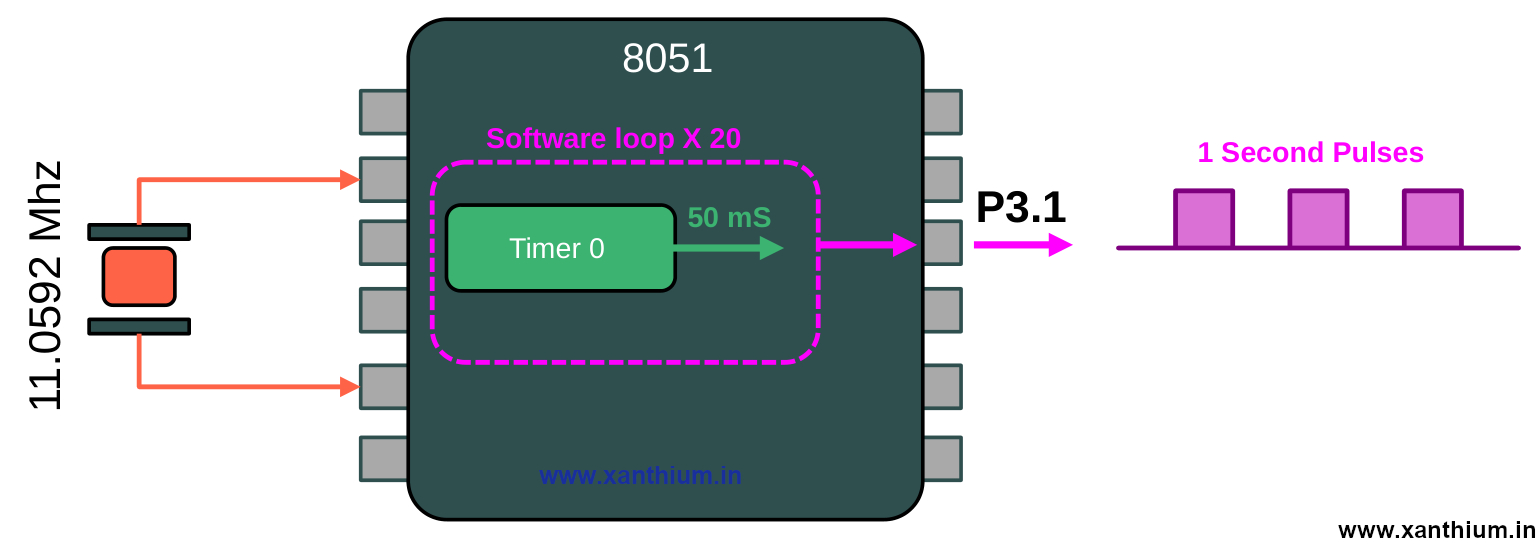
The Maximum time delay provided by the 16 bit Register of Timer0 and Timer1 for a Crystal Frequency of 11.0592MHz is 71.1 milliseconds. So we cannot generate 1Second delay directly.
To generate 1 second delay using 8051 Timer 0 , we will create a 50ms delay using Timer 0 and call it 20 times inside a loop.
To create a 50ms Delay ,
1 Tick = 1.085uS (micro seconds)

Total number of Ticks needed = Desired Time delay / Time of 1 Tick
                             = 50,000uS (microseconds)/1.085uS (micro seconds)
                             = 46,082.94 Ticks needed
Now to get the counter value to be loaded into the timer
65,536 - 46,083 = 19,453 Decimal Convert to Hex
19,453 Decimal  - > 0x4BFD (Hex)

TH0 = High Byte = 0x4B
TL0 = Low Byte  = 0xFD
Here is the full 8051 code for generating 1 second delay using Timer 0 with external clock = 11.0592 Mhz
// (c) 2026 www.xanthium.in
// Timer 0 is Configured to Generate time delay of 1 Second continously
// and blink the LED connected to P3.0 with delay of 1 second

// External Crytal Clock = 11.0592 Mhz
// Internal Timer Clock  = External Crytal Clock/12 -> 11.0592 Mhz/12
// Internal Timer Clock  =  0.9216 Mhz

// Ticks (Time Period )  = 1/(0.9216 Mhz)
//                       = 1.085uS (micro seconds)

#include <reg51.h>   //Header file used by Kiel uVision
void main(void)
{
    P3 = 0x00; // Port 3 all bits off

    TMOD = 0x01;       // -------------Timer0, Mode 1(16-bit)
                       // C/T = 0, So Timer Mode

                       // TMOD Register
                       // [G C/T M1 M0] [G C/T M1 M0]
                       // [0 0   0  0 ] [0 0   0  1 ]

while(1)
    {
        int i = 0;

        for (i = 0;i<20;i++) //Call 50ms delay 20 times = 1 Second
        {
         //Generate 50 ms Delay
          TH0 = 0x4B;        // Load high byte
          TL0 = 0xFD;        // Load low byte

          TR0 = 1;           // Start Timer0

          while(TF0 == 0); //if   TF0 = 0 stay here
                         //when TF0 = 1 Exit while loop

          TF0 = 0;         // Manually Clear the Timer overflow Flag
          TR0 = 0;         // Stop the Timer
        }

        P3 ^= 0x01; //Toggle P3.0 Bit  using XOR operative

    }//end of while(1)
}//end of main()
Configuring the Interrupts of 8051 Timers
In the previous example we learned to create various time delays using Timer0 and Timer 1 of 8051.In those programs. we were using the polling strategy to check whether the timer register had overflown or not.
We were constantly checking the TFx Flag (TF0 or TF1) using a while loop for detecting the Timer overflow.
The Timers (Timer 0 and Timer 1 ) of 8051 has interrupt capability which can be used to detect a Timer overflow. When the16 bit register Overflows the Timer Module can generate an interrupt, provided global interrupts are enabled.
Registers Needed
To Control and configure the Timer ,We will need to use the TMOD and TCON register which we have already discussed.
To set up and enable the Timer interrupts of 8051, We need to configure the IE SFR or Interrupt Enable Register of 8051.
IE SFR is also used to configure other interrupts like 8051 UART Interrupts or External Interrupt Pins.
Here the Bits positions needed for configuring the Timer 0 and Timer 1 are shown, Rest of the bit positions not required for our Timer tutorial are greyed out.
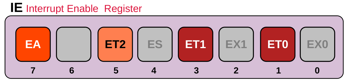
EA -> Global Enable Bit -This Bit has to be Enabled to use any interrupts inside the 8051 MCU. If the bit is disabled the Interrupts will not come.
ET0 -> Enable Timer 0 Interrupt
ET1 -> Enable Timer 1 Interrupt
ET2 -> Enable Timer 2 Interrupt
First Thing is that you have to set the EA bit so the other interrupts can occur ,Then we set the bit corresponding to the Timer we want .For Example for Timer 0 set ET0 Bit.
Once the 16 bit Timer Over Flows, the TFx Flag is Set and an interrupt is Generated. TFx Flag is automatically cleared once we exit the interrupt routine. No need to Manually Clear it
TRx Flag need to be cleared Manually.
Configuring the Timer 0 Interrupt
Now we write a small embedded C program to configure the Timer 0 to generate an interrupt when the 16 bit Timer Register overflows. After the interrupt comes we toggle P3.0 Pin inside the timer ISR .
The code below is written for Keil uVision Compiler.
// (c) 2026 www.xanthium.in
// Timer 0 is Configured to Generate an Timer 0 Interrupt
// Timer 0 overflows after 71.1ms
// P3.0 is blinked inside the isr

// External Crytal Clock = 11.0592 Mhz
// Internal Timer Clock  = External Crytal Clock/12 -> 11.0592 Mhz/12
// Internal Timer Clock  =  0.9216 Mhz
// Ticks (Time Period )  = 1/(0.9216 Mhz)
//                       = 1.085uS (micro seconds)

// 16 bit Timer Counter increments every 1.085uS (micro seconds)

// Compiler used is Kiel uVision 5

#include <reg51.h>   //Header file used by Kiel uVision
void main(void)
{
  P3 = 0x00; // Port 3 all bits off

  TMOD = 0x01; // -------------Timer0, Mode 1(16-bit)
               // C/T = 0, So Timer Mode

               // TMOD Register
               // [G C/T M1 M0] [G C/T M1 M0]
               // [0 0   0  0 ] [0 0   0  1 ]

  IE = 0x82;   // IE Register
               // [EA - ET2 ES] [ET1 EX1 ET0 EX0 ]
               // [1  0  0   0] [ 0   0   1   0  ]
               //  EA enabled
               //  ET0 Timer Interrupt enabled

  //Generate 71.1ms ms Delay
  TH0 = 0x00;        // Load high byte
  TL0 = 0x00;        // Load low byte

  TR0 = 1;           // Start Timer0

   while(1); //Wait here indefenitely


}//end of main()

//Keil Interrupt routine for Timer 0
void timer0_ISR(void) interrupt 1
{
    P3 ^= 0x01; //Toggle P3.0 Bit  using XOR operative
}
Now it is quite similar to the previous program for generating 71.1ms delay.
Here we are enabling the Global interrupt Enable Bit EA and Timer 0 Interrupt bit ET0 in the IE Register by loading the hex value 0x82 as shown below.
IE = 0x82;  // IE Register
            // [EA - ET2 ES] [ET1 EX1 ET0 EX0 ]
            // [1  0  0   0] [ 0   0   1   0  ]
            //  EA enabled
            //  ET0 Timer Interrupt enabled
We then start the Timer 0 by setting the TR0 bit and wait for the Timer0 to overflow and the interrupt to strike.
Once the Interrupt happens, the program flow is transferred to the Interrupt Service Routine for Timer 0
//Keil Interrupt routine for Timer 0

void timer0_ISR(void) interrupt 1
{
    P3 ^= 0x01; //Toggle P3.0 Bit  using XOR operative
}
Where we blink the LED connected to the P3.0.
We have not cleared the TR0 Flag ,that means that the Timer will start counting up again from 0x0000 and another Interrupt will strike in 71.1ms.
No need to reload the 16 bit register as we are using the 0x0000 value.
Keil uVision Timer Interrupt Routines Map for 8051
//Keil uVision Interrupt routine for Timer 0

void timer0_ISR(void) interrupt 1
{
   //isr handling code here
}
Here the ISR is created outside the main() .
You can change the name of ISR routine to anything you want but the function prototypes and return values should be void.
Keil uVision maps the interrupt 1 to Interrupt vector of the Timer0 overflow
void mytimer0_something(void) interrupt 1
{
   //isr handling code here
}
Here is the interrupt service routines for Timer 1.Please note that we are using interrupt 3 here
//Keil uVision Interrupt routine for Timer1

void timer1_ISR(void) interrupt 3  //interrupt 3 maps to Interrupt vector of the Timer1 overflow
{
   //isr handling code here
}
How to Create Timer ISR in SDCC
The above code is designed for Keil Compiler. If you are using the opensource compiler SDCC (Small device C Compiler) ,You will have to use a different syntax to create the ISR routines for Timer 0.
#include <8051.h>

void timer0_ISR(void) __interrupt (1);   // Forward declaration

void main(void)
{
   //all the config code here
}

// Timer0 Interrupt Service Routine
void timer0_ISR(void) __interrupt (1)
{
   P3 ^= 0x01;   // Toggle P3.0
}
In SDCC ,We use __interrupt (1) for mapping the ISR to the interrupt vector of the Timer 0 .
// Timer1 Interrupt Service Routine
void timer1_ISR(void) __interrupt (3)
{
   //isr code here
}
Generating a 1 Second Delay using 8051 Timer Interrupts
Now We have already learned about how to setup interrupts of 8051 Timer ,We will use this to generate a 1 second delay using 8051 Timer Interrupts. The embedded C Code for generating the 1 second delay using interrupts is shown below.
// (c) 2026 www.xanthium.in

// Timer0 used to Generate 1 second delay using interrupts
// Timer0 is Configured to Generate an Timer 0 Interrupt
// Timer0 overflows after 50ms
// P3.0 is blinked inside the isr every 1 second

// External Crytal Clock = 11.0592 Mhz
// Internal Timer Clock  = External Crytal Clock/12 -> 11.0592 Mhz/12
// Internal Timer Clock  =  0.9216 Mhz
// Ticks (Time Period )  = 1/(0.9216 Mhz)
//                       = 1.085uS (micro seconds)

// 16 bit Timer Counter increments every 1.085uS (micro seconds)

// Compiler used is Kiel uVision 5

unsigned char count = 0; //global variable for keeping track of number of interrupts

#include <reg51.h>   //Header file used by Kiel uVision
void main(void)
{
  P3 = 0x00; // Port 3 all bits off

  TMOD = 0x01; // -------------Timer0, Mode 1(16-bit)
               // C/T = 0, So Timer Mode

               // TMOD Register
               // [G C/T M1 M0] [G C/T M1 M0]
               // [0 0   0  0 ] [0 0   0  1 ]

  IE = 0x82;   // IE Register
               // [EA - ET2 ES] [ET1 EX1 ET0 EX0 ]
               // [1  0  0   0] [ 0   0   1   0  ]
               //  EA enabled
               //  ET0 Timer Interrupt enabled

  //Generate 50ms  Delay
  TH0 = 0x4B;   // Load high byte
  TL0 = 0xFD;   // Load low byte

  TR0 = 1;      // Start Timer0

  while(1); //Wait here indefenitely


}//end of main()

//Keil Interrupt routine for Timer 0
void timer0_ISR(void) interrupt 1
{
  //Generate 50ms  Delay
  TH0 = 0x4B;   // Load high byte
  TL0 = 0xFD;   // Load low byte

	count++; //Increment counter

	if(count >=20)// 20 × 50 ms = 1 second
	{
		count = 0;  // Reset  counter
		P3 ^= 0x01;

	}
}
Here we are running our Timer 0 in Mode 1 and will create an interrupt after 50ms has passed.
Once inside the Timer 0 ISR we update the count variable once and restart the Timer 0 again.
Here count variable is declared as Global so both the ISR and main() function can access it.
Once the count variable has reached 20 ,ie twenty 50ms interrupts have passed .We blink the LED connected to P3.0
The count is Reset to Zero.
Tags
- Log in to post comments