
In this tutorial, You will learn to program the UART of a 8051/8052 microcontroller using embedded C language and send data to a PC using Asynchronous Serial Communication .
The terminal program like Putty or Teraterm running on the PC will receive the serial data send by the 8051 and display it on the terminal.

This code can be used for developing other serial communication protocols like RS232 /RS485 with the 8051 microcontroller.
The UART Serial communication code is written in C and will work with a variety of 8051 microcontroller variants like Nuvoton W78E052DDG,NXP P89V51RD2,Microchip (formerly Atmel) AT89S51,AT89S52, silicon Labs STC89C52 etc .
Here we will be using the 8051/8052 variant W78E052DDG from Nuvoton for our Experiments. We have an 8051 development board with ADC,7Segment Display, High Current Drivers here for you to try it out .
Contents
- Source Codes
- Compilers Used
- What is Asynchronous Serial Communication
- 8051 Serial Communication Modes
- Mode 0 (Shift Register Mode)
- Mode 1 (Standard UART)
- Mode 2 (Multiprocessor Communication Mode)
- Mode 3 (Hybrid Mode)
- Programming 8051 UART in Mode 1 (Standard UART)
- Calculating 8051 UART Baud Rate Values
- Serial Communication between 8051 and a x86 (Windows/Linux) PC
- Configuring and Programming 8051 Serial Interrupts
- Registers Involved
- Configuring the Interrupts (Code)
- 8051 Serial Interrupt based Echo Program (Code)
- Differences between keil and SDCC interrupt routines
- Keil ISR for Serial Communication
- SDCC ISR for Serial Communication
- Other Serial Communication Protocols
- RS 232
- RS 485
Source Codes
All the C source codes and Project Files for programming the 8051 UART module can be downloaded from our GitHub Repo.
Browse 8051 UART Serial Programming Repo
Compilers used

Codes are compiled using Keil uVision 5 and SDCC (Small Device C Compiler)
What is Asynchronous Serial Communication
Asynchronous serial communication is a technique used in embedded systems and computers to transmit data one bit at a time over a communication line without using a shared clock signal between the sender and the receiver. Instead of a clock, both devices agree in advance on a data transmission speed called the baud rate.
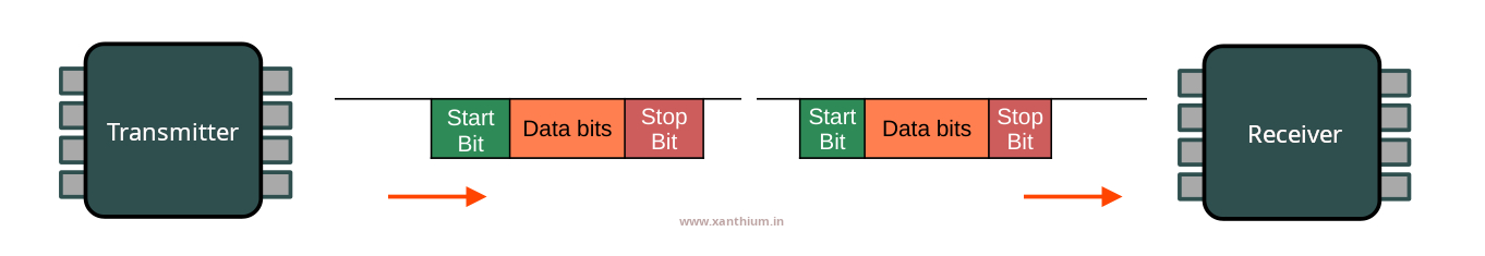
Each piece of data is sent in a structured frame that includes a start bit, a set of data bits, an optional parity bit for error checking, and one or more stop bits.
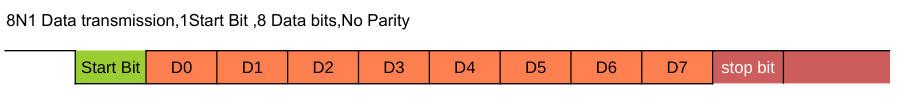
The start bit signals the beginning of data transmission, allowing the receiver to synchronize its internal clock and correctly sample the incoming bits. After the stop bit, the communication line remains idle until the next data frame is sent. This method is called asynchronous because data is transmitted only when needed, rather than in a continuous, clocked stream.
Asynchronous serial communication is commonly implemented using UART interfaces and standards such as RS-232 and RS-485. It is widely used in embedded systems for tasks such as debugging, logging, and communication between microcontrollers and peripheral devices.
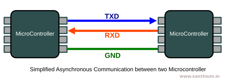
The main advantages of this communication method are its simplicity, low hardware cost, and ease of implementation. You only need three lines TXD,RXD and GND to communicate between two microcontrollers when we are using the asynchronous mode of communication as shown below.
However, it is generally slower than synchronous communication due to the additional start and stop bits and can be sensitive to timing mismatches if the baud rates of the communicating devices are not closely aligned.
8051 Serial Communication Modes
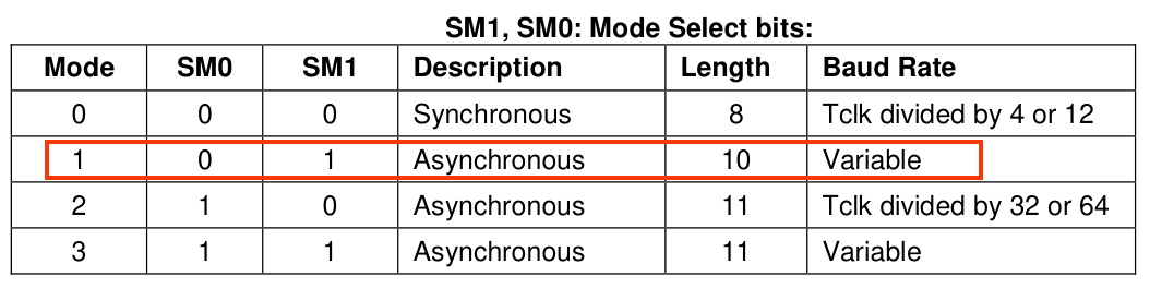
The 8051 Microcontroller provides four distinct modes of serial communication named as Mode 0, Mode 1, Mode 2 and Mode 3 ranging from simple shift registers to multi-processor communication.
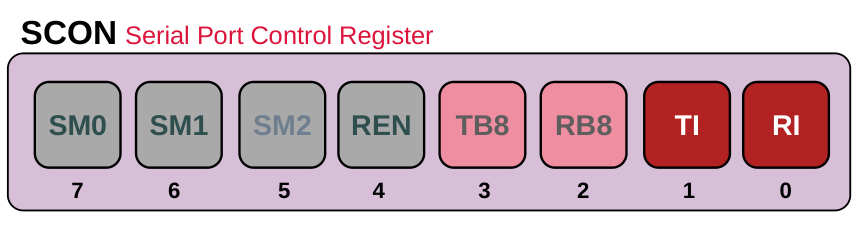
These Modes are controlled by the SMx bits in the (Serial Control ) SCON register.
The Different modes of serial communication in 8051 are as follows
8051 UART Mode 0 also known as Shift Register Mode
In this mode, serial data enters and exits through the RXD pin, while the TXD pin outputs the shift clock. This is typically used to expand the I/O ports of the microcontroller using external shift registers (like the 74HC595).
This is a synchronous Mode of communication in which data send or received through the RXD pin is synchronized with the clock coming the TXD pin.
8051 UART Mode 1 also known as Standard UART
The 8051 Microcontroller's UART Mode 1 is the most widely used configuration for serial communication. It is a 10-bit full-duplex UART, meaning it can send and receive data simultaneously using a standard frame format compatible with most PC serial ports and modern peripherals.
This is also the mode used for RS232 and RS485 Communication using the 8051 MCU.
Unlike Mode 0 or Mode 2 (which have fixed baud rates), Mode 1 has a variable baud rate. It relies on the overflow rate of Timer 1.If you want to know more about 8051 Timers .
8051 UART Mode 2 ( Multiprocessor Communication Mode )
While Mode 1 is the standard flexible UART, Mode 2 is the high-speed, fixed-baud-rate alternative. It is often used for high-speed communication between two microcontrollers where the flexibility of a timer is not required.
In Mode 2, the 8051 uses an 11-bit frame and a baud rate derived directly from the crystal frequency .The 9th bit is excellent for Multiprocessor Communication Mode. A master can send a byte with the 9th bit = 1 to signal an Address, and 9th bit = 0 to signal Data. Slaves only wake up when they receive an address byte.
Mode 2 does not use Timer 1. Instead, the baud rate is a fixed fraction of the oscillator frequency (Osc/32 or Osc/64). This makes it significantly faster than Mode 1 .
This Mode (Mode2) leaves Timer 1 free to be used for other tasks (like PWM, delays, or interval counting).
8051 UART Mode 3
UART Mode 3 is essentially a combination mode where the 11-bit frame structure of Mode 2 is combined with the variable baud rate flexibility of Mode 1.
Unlike Mode 2, which has a fixed speed, Mode 3 uses Timer 1 (or Timer 2 in some 8052 variants) to determine the baud rate. This allows you to communicate with standard PC serial ports while still having that extra 9th bit available.
Programming 8051 UART in Mode 1 (Standard UART)
In this section we will learn how to configure and program the UART of a 8051/8052 microcontroller variant like AT89S51 ,AT89S52,W78E052D to communicate with an external Computer like a Windows PC or Linux PC Serial Port using Asynchronous Serial Communication.
In order to perform Serial communication with the serial port of a Computer we need to configure the SCON,PMOD register of the 8051 MCU so the UART is put in correct mode and the correct baud rate is selected. We may need to configure the interrupt registers of 8051 like IE ,if we plan to perform interrupt driven serial communication using 8051 UART.
In the Mode1, the Baud rate of the 8051 UART is provided by the Timer 1 running in 8 bit Auto reload mode ,so when you are using the 8051 UART in Mode 1 ,you will not be able to use Timer 1 for other timing tasks.
8051 UART Registers
The Major Registers needed for configuring the 8051 are the following
PCON (Power Control SFR),
SCON (Serial Control SFR)
and SBUF (Serial Port Buffer )
PCON (Power Control SFR)
contains the SMODx bits (SMOD0,SMOD) which are used for doubling the baud rates in mode 1,mode2 and mode 3.
SMOD bit is used to double the serial port baud rate in mode 1, 2, and 3 when set to 1.
When SMOD bit = 1 ,The Internal clock used for generating Baud rate is divided by 16,therby doubling the baud rate.
By default SMOD bit = 0 ,The Internal clock used for generating Baud rate is divided by 32
The PCON register is not bit-addressable (unlike SCON). You must write to the entire register at once.
- SMOD0 bit is used for Framing error detection and is not relevant here.
SBUF Register (Serial Port Buffer )
SBUF (Serial Buffer) is the register used for all serial data transfers. While it appears as a single register address (99H), it is actually physically composed of two separate, independent 8 bit registers.
One is the receive register, and the other is the transmit buffer.
When you read any data from the SBUF using software ,the reading is done from the Receive Register.
Rxed_Data = SBUF; //Reading data from SBUF Register of 8051/8052 UARTWhen you write data to the SBUF using software ,the data is written into the Transmit Buffer.
SBUF = 'A' ; //writing data to SBUF Register of 8051/8052 UARTThe UART hardware immediately begins shifting this byte out bit-by-bit through the TXD pin. Once the transmission is finished, the TI (Transmit Interrupt) flag is set.
Data is always transmitted and received with the Least Significant Bit first.
This full duplex design allows the 8051 to send data and receive data at the exact same time without the two processes interfering with each other. If they shared a single physical register, the controller would have to operate in half duplex .
SCON (Serial Control SFR)
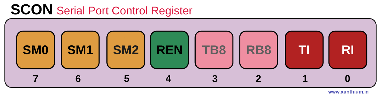
TI Bit (Transmit Interrupt Flag )
Its main job is to let the CPU know that the serial port has finished transmitting a character (byte) and is ready for the next one.
When you write a byte of data to the SBUF (Serial Buffer) register, the hardware starts shifting those 8 bits out (LSB first ) via the TXD pin. As soon as the stop bit of that byte has been transmitted, the hardware automatically sets the TI bit to 1.
If Serial Interrupts are enabled, When the UART hardware sets the T1 bit to 1 (after sending a byte), an interrupt is triggered.
The 8051 UART hardware sets the bit to 1 automatically when transmission is complete. You have to clear the TI bit in software (after servicing the interrupt )
RI Bit (Receive Interrupt Flag )
Its main job is to signal the CPU that a complete byte of data has been received via the serial port and is sitting in the SBUF (Serial Buffer) register, waiting to be read.
Once a full byte (usually 8 bits plus a stop bit) has arrived, the hardware automatically sets the RI bit to 1.
If serial interrupts are enabled , the CPU immediately jumps to the Serial Interrupt Service Routine (ISR)
The 8051 UART hardware sets the RI bit to 1 automatically when transmission is complete. You have to clear the RI bit in software (after servicing the interrupt )
Both TI Bit (Transmit Interrupt Flag ) and RI Bit (Receive Interrupt Flag ) share the same interrupt vector (0023H), so your code must check which flag triggered the interrupt.
RB8 Bit (Receive Bit 8)
When the 8051 is operating in Mode 2 or Mode 3 (9-bit serial modes), the incoming data frame consists of 9 bits. The first 8 bits are funneled into the SBUF register, but the 9th bit is dropped into the RB8 slot. The behavior of RB8 actually changes slightly depending on which serial mode you are using.
TB8 Bit (Transmit Bit 8)
It serves as the 9th data bit to be transmitted when the serial port is operating in Mode 2 or Mode 3.
Standard serial communication usually uses 8 bits. However, in certain modes, the 8051 uses a 9-bit format. Since the SBUF (Serial Buffer) register can only hold 8 bits, the TB8 bit acts as a temporary holding cell for that extra 9th bit
Parity bit and in Multi Processor Communication (to distinguish between data or address)
REN Bit (Receive Enable)
This bit is used to Enable or Disable the 8051 UART Receiver.If the bit is disabled or incoming data bytes are ignored.
When the receiver is Enabled. The hardware actively monitors the RXD line for a START bit ,When it detects one, it begins shifting in data.
Disabling the REN may be useful in certain cases like saving Power or to protect the CPU from spurious signal noise coming from a noisy RXD input line.
SM2 Bit
Used in Multiprocessor Communication.
SMx Bits (SM0,SM1)
These 3 bits are used for selecting the different modes of the 8051 UART .
Calculating 8051 UART Baud Rate Values
Here we will learn about generating and calculating different baud rate values for the 8051/8052 UART. Here we are using the W78E052D Microcontroller (8051/8052 variant) from Nuvoton.
There are different ways of generating Baud rate values for 8051/8052 Microcontroller.
Generating Baud Rate values using Timer 1 of 8051
Generating Baud Rate values using Timer 2 of 8052
Generating Baud Rate values using Timer 1 of 8051
The most commonly used method for generating baud rate for 8051 variants is to use the Timer 1 in Mode 2 Auto Reload Mode.
The below image shows how the clock is sourced for generating the correct baud rate value using Timer 1 of 8051 in Auto Reload Mode.
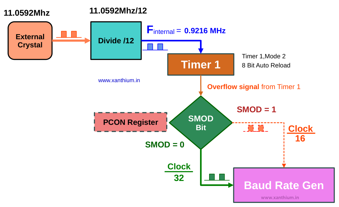
Here we are using the external crystal frequency of 11.0592Mhz instead of 12.0 Mhz .
This is because 11.0592 Mhz is perfectly divisible by the standard baud rates (9600, 19200, etc.), resulting in 0% error. Using 12 MHz results in slight timing offsets that can cause garbage data during serial communication.
Now the external crystal Frequency is divided by 12 resulting in an internal effective clock of 0.9216 MHz or 921.6KHz. This clock is fed into the Timer 1 operating in Mode 2 (8bit Auto Reload).
In Mode 2 (8bit Auto Reload) configuration the 16 bit Register of Timer 1 acts as Two 8 bit Registers
TL1 (Timer Low 1) -> Acts as the Counter
TH1 (Timer High 1) ->Holds the 8 bit value that will be loaded into TL1
The TL1 will start counting from the value loaded into it from TH1 to the maximum 8 bit value ie 255 (8bit).Once TL1 reaches 255 it will overflow, generating a pulse.
After the overflow ,The TL1 will immediately load the value from TH1 and starting counting up again.
This pulse signal is divided by either 32 or 16 ,depending upon the Status of SMOD bit in PCON register of 8051 before giving it to the Baud Rate Generator
By default SMOD =0 ,so pulse is divided by 32.
Why we are not using Timer Mode 1,
In other modes (like Mode 1, 16-bit), once the timer overflows, it starts counting from 0 unless you manually stop the code and reload the value. This manual reloading creates a small time delay, which causes timing drift.
In Mode 2, because the hardware reloads TL1 instantly, the timing remains perfectly consistent. This is why Mode 2 is the gold standard for generating stable baud rates for serial communication.
You can find a detailed tutorial on configuring the Timers of 8051 here.
Formula for calculating the Baud rate
Her you can see the formula for calculating the Baud rate of 8051.

When SMOD = 0 , 2SMOD = 20 = 1 which means it is 1/32
When SMOD = 1 , 2SMOD = 21 = 2 which means it is 2/32 = 1/16
Here fosc = 11.0592 MHz
Now we already knew the baud rate we want to communicate with ,what we really want to know is the value that should be loaded into the TL1 register of 8051 Timer 1 for a specific baud rate.
So we rewrite the equation.
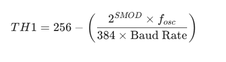
Here The value 384 comes from 12 X 32 (the machine cycle divisor times the UART internal divisor).
If you plug the values in for 11.0592 MHz and SMOD =0 ,you will get 253 decimal or 0xFD hex.
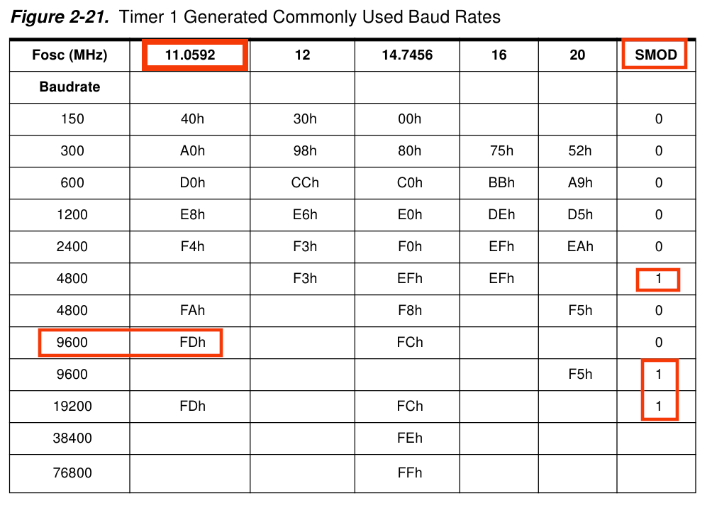
Calculating 8051 Baud Rate Values (the Easy Way)
The easiest and simple way to find out the correct TH1 values for 8051 is to go into the datasheet or user manual and just copy the correct values from the table below.
Basic 8051 UART Configuration Code in C
Now we will create a simple embedded c code for sending a character A from our 8051/8052 microcontroller to another PC using Serial Port.
The 8051 will configure the UART in Mode 1 and use the Timer 1 to generate a Baud Rate of 9600 bps.
The below code can be compiled using both Keil uvision 5 and SDCC compilers.
// (c) 2026 www.xanthium.in
// 8051 UART  Programming Tutorial
// Basic 8051 UART Configuration Code in Embedded C for communicating at 9600bps
// External Crytal Clock = 11.0592 Mhz
// Compiler used is Kiel uVision 5

#include <reg51.h>   //Header file used by Kiel uVision

// #include <8052.h> //Header file for sdcc

void main(void)
{
   TMOD = 0x20; // Timer 1, Mode 2 8-bit auto-reload
   TH1  = 0xFD; // 9600 Baud rate @ 11.0592MHz
   SCON = 0x50; // Mode 1 8-bit UART, Enable Receiver (REN=1)
                // [SM0 SM1 SM2 REN TB8 RB8 TI RI ]
                // [0    1   0   1   0   0   0  0 ] = 0x50

   TR1  = 1;      // Start Timer 1

   SBUF = 'A';      // Load char A into Serial Buffer
   while (TI == 0); // Wait until Transmission Interupt flag is set
   TI = 0;          // Clear the flag for the next character

   while(1); //stop here
}
If you run this program. You can receive the character A on the Putty terminal as shown below.
What is the Maximum Baud Rate for 8051
The maximum baud rate for an 8051 depends entirely on your crystal frequency and your SMOD bit setting. So in our case it would be around 19200 bps for 11.0592MHz.
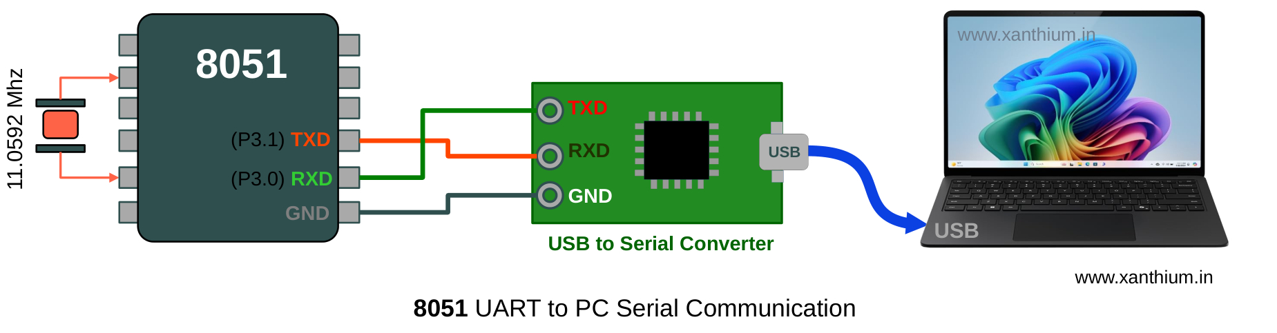
Serial Communication between 8051 MCU and a x86 (Windows/Linux) PC
Now in the real world your 8051 microcontroller may need to transmit some data from a sensor to a PC running Windows 11 or Linux ,for those occasions we are going to use the 8051 UART in Mode 1 to send and receive data.
The above block diagram shows the hardware connections needed to communicate with an x86 PC (Laptop) from a 8051 Microcontroller using its UART.
Here the UART signals are connected to a USB to Serial converter to turn TTL signals to USB which the PC understands.
A terminal Program like Putty is used to display the data send from 8051.
Hardware Connections between 8051 & PC
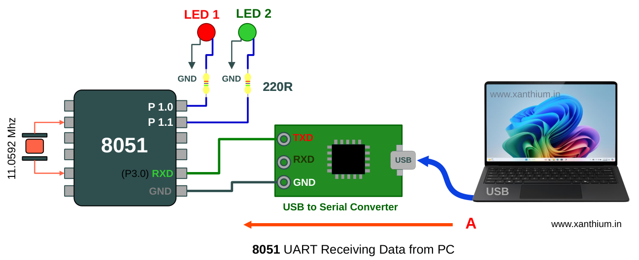
As Most computers today lack a traditional serial port ,we are using a USB to Serial Converter between our 8051 and the PC (Windows/Linux/Mac).
Here we are using USB2SERIAL,which is a USB to Serial/RS232/RS485 converter. The converter can also be used to talk with both RS232 and RS485 devices.
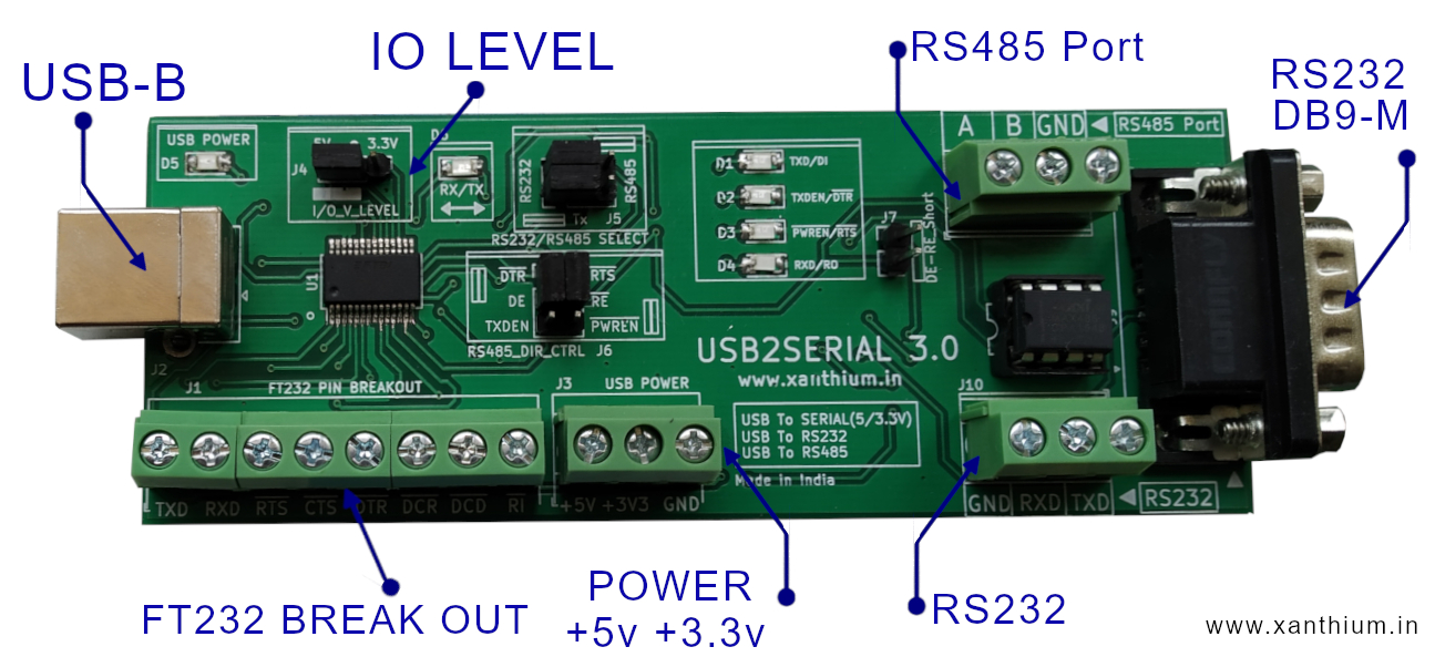
The 5V TTL signals coming from the 8051 MCU is converted to the USB signal Levels and is received by the PC using a Virtual Com Port (Windows ) or Virtual Terminal on Linux .
Here we will be using the cross platform PuTTY Program to display the data on your computer terminals.
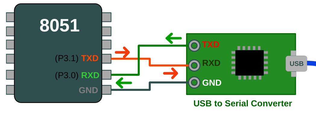
Please note that in the above image the TXD and RXD pins are crossed.
TXD pin of the 8051 is connected to the RXD pin of the USB to Serial Converter
RXD pin of the 8051 is connected to the TXD pin of the USB to Serial Converter
So when the 8051 transmits any data (TXD) to the PC using its UART ,the data is received by the Receive Buffer of the PC's Serial Port (this will be abstracted out by the driver software of the USB to Serial Converter).
Transmitting Data from 8051 to PC
Now that the connections are complete we can write a small program that will send a text string to the PC from your 8051 Microcontroller 's UART using a 3 wire serial connection (TXD,RXD & GND).
Here we will be communicating at 9600bps with the PC .
The C code for transmitting data from 8051 UART to PC is shown below.
// (c) 2026 www.xanthium.in
// 8051 UART Programming Tutorial
// 8051 Microcontroller sends " Hello World from 8051 To PC" to your x86 PC
// External Crytal Clock = 11.0592 Mhz
// Compiler used is Kiel uVision 5
#include <reg51.h> //Header file used by Kiel uVision
void main(void)
{
char message[] = "Hello World from 8051 To PC @9600bps \r\n"; //\r\n (CR LF) for proper formatting in Putty
int i = 0;
TMOD = 0x20; // Timer 1, Mode 2 8-bit auto-reload
TH1 = 0xFD; // 9600 Baud rate @ 11.0592MHz
SCON = 0x50; // Mode 1 8-bit UART, Enable Receiver (REN=1)
//[SM0 SM1 SM2 REN TB8 RB8 TI RI ]
//[0 1 0 1 0 0 0 0 ]
/*
//change baudrate to 19200 using SMOD bit
PCON |= 0x80; // Sets Bit 7 (SMOD) to 1; OR ing with PCON
// [SMOD SMOD0 RESERVD POR GF1 GF0 PD IDL]
// [1 0 0 0 0 0 0 0] = 0x80
*/
TR1 = 1; // Start Timer 1
//send the message
while(message[i] != '\0')
{
SBUF = message[i]; // Load a char into Serial Buffer
while (TI == 0); // Wait until Transmission Interupt flag is set
TI = 0; // Clear the flag for the next character
i++;
}
while(1); //stop here
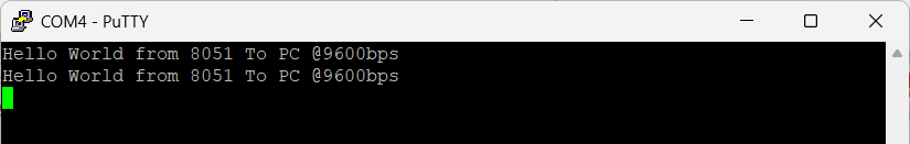
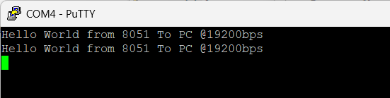
} Once the Code is downloaded .8051 will transmits the message to PC where it is received by Putty Program and displayed on the Command line.
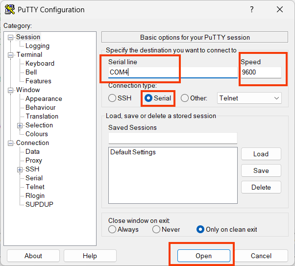
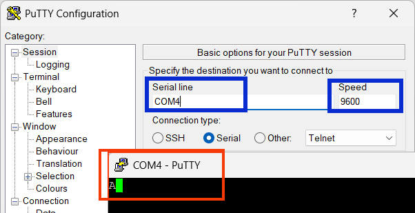
Please enter the correct COM Port Number and the Baud Rate (9600). The Press Open.
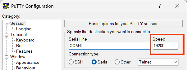
Double the Baud Rate of 8051 UART Communication
Now you can double the baud rate from 9600 to 19200 bps by setting the SMOD bit in PCON register as shown below.
// C code for Doubling the Baud Rate of 8051 UART
// change baudrate to 19200 using SMOD bit

PCON |= 0x80;  // Sets Bit 7 (SMOD) to 1; OR ing with PCON
               // [SMOD SMOD0 RESERVD POR GF1 GF0 PD IDL]
               // [1      0    0       0   0   0   0   0] = 0x80
Here we are setting the SMOD bit using an OR operation so that the other bits in PCON register are not disturbed.
On Running this code make sure that the Baud Rate =19200bps.
Now you will receive the Text string
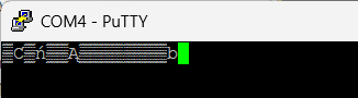
Trouble Shooting Tip
If you are getting garbled data, as shown below there is a mismatch in the baud rate between PC and 8051.
8051 UART Receiving Data from PC
Now we are going to receive some data from PC using 8051 UART . To make the 8051 UART ready for data reception you should enable the REN bit (Receive Enable) in the SCON register.
The value 0x50 does that for you as shown in the below image.
 SCON = 0x50;   // Mode 1 8-bit UART, Enable Receiver (REN=1)
                 // [SM0 SM1 SM2 REN TB8 RB8 TI RI ]
                 // [0    1   0   1   0   0   0  0 ]
Once the 8051 UART has received a complete byte from outside .The Hardware will set the RI bit in the SCON register to 1.
while (RI == 0); // Wait here until data is received (RI becomes 1)Here we will use a while loop to check for this condition,(Polling strategy).
Once the data is received .We should manually clear the RI bit.
Now you can read the data from the SBUF register using
Rxed_Data = SBUF;// Read data from the 8051 UART Buffer SBUFHere is a Full code for Receiving a byte from PC using 8051 UART
// (c) 2026 www.xanthium.in
// Embedded C Program to Read Data from UART of 8051
// External Crystal Clock = 11.0592 Mhz
// Compiler used is Kiel uVision 5

#include <reg51.h>   //Header file used by Kiel uVision
//#include <8052.h>  //for SDCC
void main(void)
{
  char Rxed_Data = 0;
  P1   = 0x00;
  TMOD = 0x20;   // Timer 1, Mode 2 8-bit auto-reload
  TH1  = 0xFD;   // 9600 Baud rate @ 11.0592MHz
  SCON = 0x50;   // Mode 1 8-bit UART, Enable Receiver (REN=1)
                 // [SM0 SM1 SM2 REN TB8 RB8 TI RI ]
                 // [0    1   0   1   0   0   0  0 ]
  TR1  = 1;      // Start Timer 1

  //Read incoming data
  while (RI == 0); // Wait until data is received (RI becomes 1)
  RI = 0;          // Manually Clear RI=0
  Rxed_Data = SBUF;// Read the 8051 UART Buffer SBUF

  while(1); //stop here
}
8051 LED Control from PC Serial Port
Now we will build a Small 8051 program that will receive characters from the PC and control LED's connected to Port 1 of 8051.
Here 8051 and the PC are connected using a three wire serial communication link as shown in the below image.
PC will send ASCII Character A to turn ON LED 1 connected to P1.0
PC will send ASCII Character B to turn ON LED 2 connected to P1.1
PC will send ASCII Character C to turn OFF Both LED's.
The 8051's LEDs will be controlled by sending characters from the PC using PuTTY over a serial connection.
Here is the full code for 8051 LED control over Serial Port from Windows PC using Putty.
// (c) 2026 www.xanthium.in
// 8051 UART  Programming Tutorial
// Embedded C Program to control LED's connected to Port P1 0f 8051 MCU
// Compiler used is Kiel uVision 5

#include <reg51.h>   //Header file used by Kiel uVision

void Delay_ms(unsigned int ms);

void main(void)
{
  char Rxed_Data = 0;

  P1   = 0x00;
  TMOD = 0x20;   // Timer 1, Mode 2 8-bit auto-reload
  TH1  = 0xFD;   // 9600 Baud rate @ 11.0592MHz
  SCON = 0x50;   // Mode 1 8-bit UART, Enable Receiver (REN=1)
                 // [SM0 SM1 SM2 REN TB8 RB8 TI RI ]
                 // [0    1   0   1   0   0   0  0 ]


  TR1  = 1;      // Start Timer 1

  //loop continously waiting for data from PC side
  while(1)
  {
    while (RI == 0);// Wait until data is received (RI becomes 1)
    RI = 0; //clear RI Flag
    Rxed_Data = SBUF;

    //Selection Logic ,You can use switch() also instead of if()
    if(Rxed_Data == 'A' )
       P1 |= 0x01;        //Light up P1.0
    if(Rxed_Data == 'B' )
       P1 |= 0x02;        //Light up P1.1
    if(Rxed_Data == 'C' )
       P1 = 0x00;         //Switch off Both LED's

    Delay_ms(500); //delay function
  }
}

void Delay_ms(unsigned int ms)
{
   unsigned int i, j;
   for(i = 0; i < ms; i++)
      {
       for(j = 0; j < 120; j++); // Approximate for 11.0592 MHz
      }
}
Configuring and Programming 8051 Serial Interrupts
In all the previous examples we were using a while loop to trap the CPU in a specific point until data arrived or is transmitted .This method known as polling is quite waste full in terms of Power and CPU cycles.
The correct way to program the UART is to use interrupts that trigger the CPU when a specific condition has happened and the CPU will do its work inside the Interrupt Service Routine.
Here we will learn to configure and program the Serial Interrupts of 8051 UART for communicating with external devices.
The UART of 8051 is capable of generating Two types of Interrupts
An Interrupt is Generated when Data is transmitted
An Interrupt is generated when Data is received.
Both Serial Transmit and Serial Receive Interrupts share the same interrupt vector (address 0023H). This means when the interrupt triggers, the CPU doesn't automatically know if it's because it received something or finished sending something. You have to check manually inside the ISR (Interrupt Service Routine) to which interrupt has happened.
Registers Involved
The Major registers involved are
IE (Interrupt Enable) Register
SCON Register
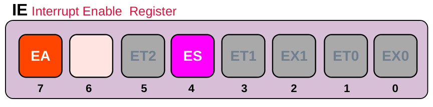
You have to Enable the EA bit of the IE Register for any Interrupts to happen.
You have to Enable the ES bit of the IE Register for enabling the Serial Interrupts.
You can do that by
IE = 0x90; // Sets EA = 1 and ES = 1
           //[EA - ET2 ES ET1 EX1 ET0 EX0 ]
           //[ 1 0  0  1   0   0   0   0  ] = 0x90
Once the interrupts are configured you can use the TI and RI bits to check which action has triggered the Interrupt.
TI is set to 1 when the UART is finished Transmitting
RI is set to 1 when the UART has finished Receiving a Byte
Unlike some other 8051 interrupts (like Timer 0), the hardware does not clear the RI or TI flags for you. You must clear them in your code, or the interrupt will trigger endlessly in a loop.
Configuring the Interrupts
Here is a small program to configure the interrupts of 8051 when you send a data to the 8051 the Receive interrupt will trigger and LED connected to P1.0 will light up
By setting the IE register to 0x90, the program enables the Serial Interrupt (ES) and Global Interrupt (EA), allowing the CPU to stay in an idle while(1) loop rather than wasting cycles polling flags.
When a byte is received, the hardware triggers the Serial_ISR (at vector address 0023H), which toggles P1.0 as a visual indicator and manually clears the RI flag to prepare for the next byte.
// (c) 2026 www.xanthium.in
// 8051 UART  Programming Tutorial
// Embedded C Program to configure the serial interrupts of 8051
// External Crytal Clock = 11.0592 Mhz
// Compiler used is Kiel uVision 5
#include <reg51.h>   //Header file used by Kiel uVision

void main(void)
{


   P1   = 0x00;
   TMOD = 0x20;   // Timer 1, Mode 2 8-bit auto-reload
   TH1  = 0xFD;   // 9600 Baud rate @ 11.0592MHz
   SCON = 0x50;   // Mode 1 8-bit UART, Enable Receiver (REN=1)
                     //[SM0 SM1 SM2 REN TB8 RB8 TI RI ]
                     //[ 0   1   0   1   0   0   0  0 ]

      // Configure Interrupts
      IE = 0x90; // Sets EA = 1 and ES = 1
              //[EA - ET2 ES ET1 EX1 ET0 EX0 ]
              //[ 1 0  0  1   0   0   0   0  ] = 0x90

      TR1  = 1;      // Start Timer 1

      while(1); //Stay here until interrupts happen

}
//Keil specific Interrupt
void Serial_ISR(void) interrupt 4
{
   if (RI == 1)
   {
       // Data received
       P1 ^= 0x01;    //toggle P1.1
       RI = 0;        // MUST clear RI manually
   }

   if (TI == 1)
   {

       TI = 0; // MUST clear TI manually
   }
}
Please note that
void Serial_ISR(void) interrupt 4 //interrupt 4 Serial interrupt vector
{
}
Here interrupt 4 is the Serial interrupt vector (keil specific)
8051 Serial Interrupt based Echo Program
This code implements an interrupt-driven serial echo system for the 8051 microcontroller.
It initializes Timer 1 in 8-bit auto-reload mode to generate a 9600 baud rate and configures the UART for 8-bit communication with the receiver enabled.
By setting the IE register to 0x90, it enables global and serial interrupts, allowing the CPU to remain in an idle while(1) loop until data arrives.
When a byte is received, the Serial_ISR is triggered, which toggles an LED on P1.0, captures the incoming data from SBUF, and immediately transmits it back to the sender.
The routine also handles the completion of transmissions by toggling P1.1,
// (c) 2026 www.xanthium.in
// 8051 UART  Programming Tutorial
// Embedded C Program to configure the serial interrupts of 8051
// Interrupts based echo Program
// External Crytal Clock = 11.0592 Mhz
// Compiler used is Kiel uVision 5
#include <reg51.h>   //Header file used by Kiel uVision
char received_data = 0x00;
void main(void)
{
   P1   = 0x00;
   TMOD = 0x20;   // Timer 1, Mode 2 8-bit auto-reload
   TH1  = 0xFD;   // 9600 Baud rate @ 11.0592MHz
   SCON = 0x50;   // Mode 1 8-bit UART, Enable Receiver (REN=1)
                     //[SM0 SM1 SM2 REN TB8 RB8 TI RI ]
                     //[ 0   1   0   1   0   0   0  0 ]
   // Configure Interrupts
   IE = 0x90; // Sets EA = 1 and ES = 1
              //[EA - ET2 ES ET1 EX1 ET0 EX0 ]
              //[ 1 0  0  1   0   0   0   0  ] = 0x90

   TR1  = 1;      // Start Timer 1

   while(1); //Stay here until interrupts happen

}

//Keil specific Interrupt
void Serial_ISR(void) interrupt 4
{
   if (RI == 1)
   {
       // Data received
       P1 ^= 0x01;           //toggle P1.0
       received_data = SBUF; //get data from PC
       RI = 0;        // MUST clear RI manually
       SBUF = received_data ; //send data back
   }

   if (TI == 1)
   {
     P1 ^= 0x02;           //toggle P1.1
     // Transmission finished!
     TI = 0; // MUST clear TI manually
   }
}
Differences between keil and SDCC interrupt routines
While both Keil C51 and SDCC (Small Device C Compiler) target the 8051, their syntax for defining Interrupt Service Routines (ISRs) differs because they use different methods to tell the linker where to place the function in memory.
The most immediate difference is how you declare the interrupt number and the function attributes.
Keil ISR for Serial Communication
#include <reg51.h>   //Header file used by Kiel uVision
void main(void)
{
  //main code
}

void Serial_ISR(void) interrupt 4 //interrupt 4 Serial interrupt vector for keil
 {
 	// Code here
 }
SDCC ISR for Serial Communication
#include <8052.h>   //Header file used by SDCC
void main(void)
{
  //main code
}
void Serial_ISR(void) __interrupt (4) //interrupt 4 Serial interrupt vector for SDCC
{
   // Code here
}
Other Serial Communication Protocols
The 8051 UART serves as the foundation for serial communication, generating the logic-level (TTL) timing and data framing required to send bits in a sequence. While the UART handles the digital protocol, it lacks the electrical power to transmit signals over long distances or resist industrial noise.
This is where RS232 and RS485 come in as physical layer standards; they translate the 8051’s delicate 0V/5V signals into more robust voltages.
RS232 Protocol
RS232 Protocol is typically used for simple, short-range point-to-point connections (like a PC to a peripheral),
If you want to connect your 8051 UART to an RS232 network you should use a Level Translator chip like MAX232 to convert TTL Level signals to RS232 Levels.
To Learn more about RS232 check out 8051 UART Programming in Keil C51: RS232 Serial Data Transfer to PC with MAX232
RS485 Protocol
RS485 uses differential signaling to allow for high-speed, long-distance communication across a "multi-drop" network of up to 32 devices.
If you want to connect your 8051 UART to an RS232 network, Do check out our tutorial How to Interface 8051 with RS485 for Long Distance Serial Data Transfer
Together, they allow a simple microcontroller to communicate reliably across a desk or an entire factory floor by bridging the gap between internal digital logic and external electrical environments.
- Log in to post comments