
We will learn to design and build an 4 channel LM35 temperature sensor Signal conditioner amplifier circuit based on the popular opamp LM324 using Kicad.
In the second section we will learn to interface four LM35 temperature sensors with an Arduino to monitor the temperature of a PC or Laptop and log it using serial monitor.
We also has a detailed video tutorial on designing the amplifier board on YouTube ,Links to video below.
Contents
- Design of LM35 Amplifier
- PC temperature Monitoring and Logging using LM35 and Arduino
LM35 amplifier features
Main features of our LM35 Amplifier board are.
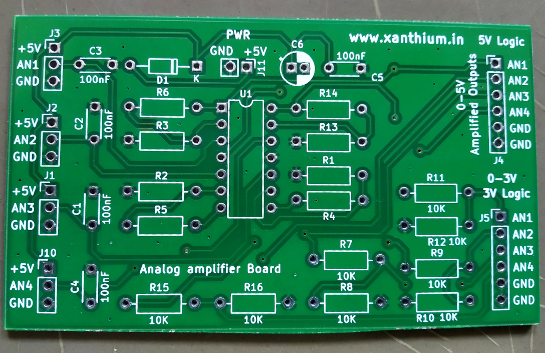
- The board consists of 4 analog channels for connecting the outputs of the LM35 chip and 4 output channels that gives the amplified output of the LM35 chip in the range of 0-5V, the Gain of all 4 channels is around 3.7.
- The board also has 4 amplified outputs that gives the amplified voltage in the range from 0-3V ,making it easier to interface LM35 to 3V tolerant microcontrollers like MSP430,STM32
- The board can also be used as a general purpose amplifier board that you can use to interface with other analog sensors and works with both 5V and 3.3 tolerant microcontrollers.
- The board is designed with Kicad 6.0 and the video tutorial teaches you how to design a circuit board from schematics to PCB with KICAD 6.0 EDA.
- All the components used in the circuit are through hole components which helps the user to build the circuit in true DIY fashion and learn valuable soldering skills.
- Board power supply 0-30V DC
The board can be used to monitor temperature from 4 different sources at the same time (below image) and can be used for building your own Arduino data acquisition and logging system as shown below.

Download Kicad Project / Circuit Diagram
You can find the Kicad Project, Circuit diagram and datasheet files used in this tutorial from our Github repo.
- Download LM35 4-channel small signal amplifier for Microcontroller GitHub Repo as zip
- Browse LM35 4-channel small signal amplifier for Microcontroller GitHub Repo
Datasheets
- LM324 Quadruple Operational Amplifier datasheet
- LM35 Precision Centigrade Temperature Sensor datasheet
Basic Block Diagram
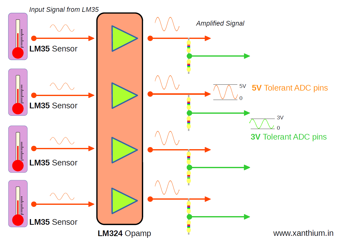
The above image show the basic block diagram of the 4 channel LM35 based temperature sensor board.
The board along with Arduino or other Microcontroller can be used to monitor and control temperature from 4 different sources at the same time and can be used for building your own USB or Serial data acquisition system.
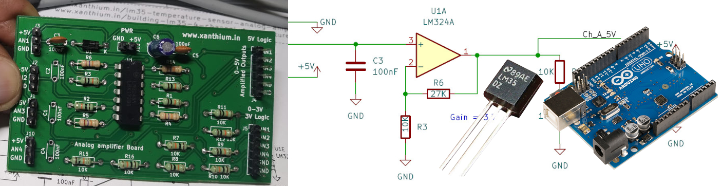
The Board has four LM35 temperature sensors whose outputs are fed into an LM324 quad opamp.
The opamp amplifies the signal (0-5V range) in such a way that the max temperature voltage of the LM35 is near 5V.This section allows the sensor to be interfaced with 5V logic level Microcontrollers like AVR ATmega328P,Arduino,PIC16F etc.
The Output is also given to a potential divider network which scales the voltage in 0-3V range. Here max temperature voltage of the LM35 is around 3V.This section allows the sensor to be interfaced with 3V logic level Microcontrollers like MSP430.
The board
Video Explanation of the Block diagram
About LM35 Temperature sensor IC
The LM35 series are precision integrated-circuit temperature devices with an output voltage linearly proportional to the Centigrade temperature scale. The LM35 device does not require any external calibration or trimming to provide typical accuracies.
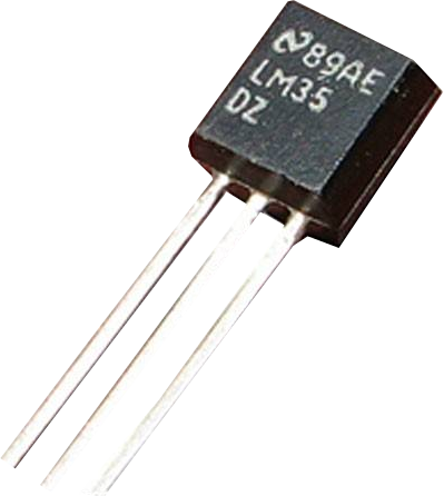
The device can be used with single power supplies, or with plus and minus supplies. The LM35 device is rated to operate over a −55°C to 150°C temperature range,
As the LM35 device draws only 60 μA from the supply, it has very low self-heating of less than 0.1°C in still air.
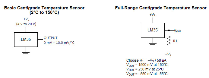
In our case we will use the temperature sensor from 2 to 150 Celsius range only .
We will be using a single 5V supply to power the chip.
LM324 Opamp Amplifier Design
LM35 chip generates 10mV for ever 1 degree Celsius rise ,so for a room temperature of 28°C ,the chip will generate 280mV or 0.28V. Low voltage signals like this are prone to interference from noise sources which may corrupt the signal. So we are using an opamp to boost the signal.
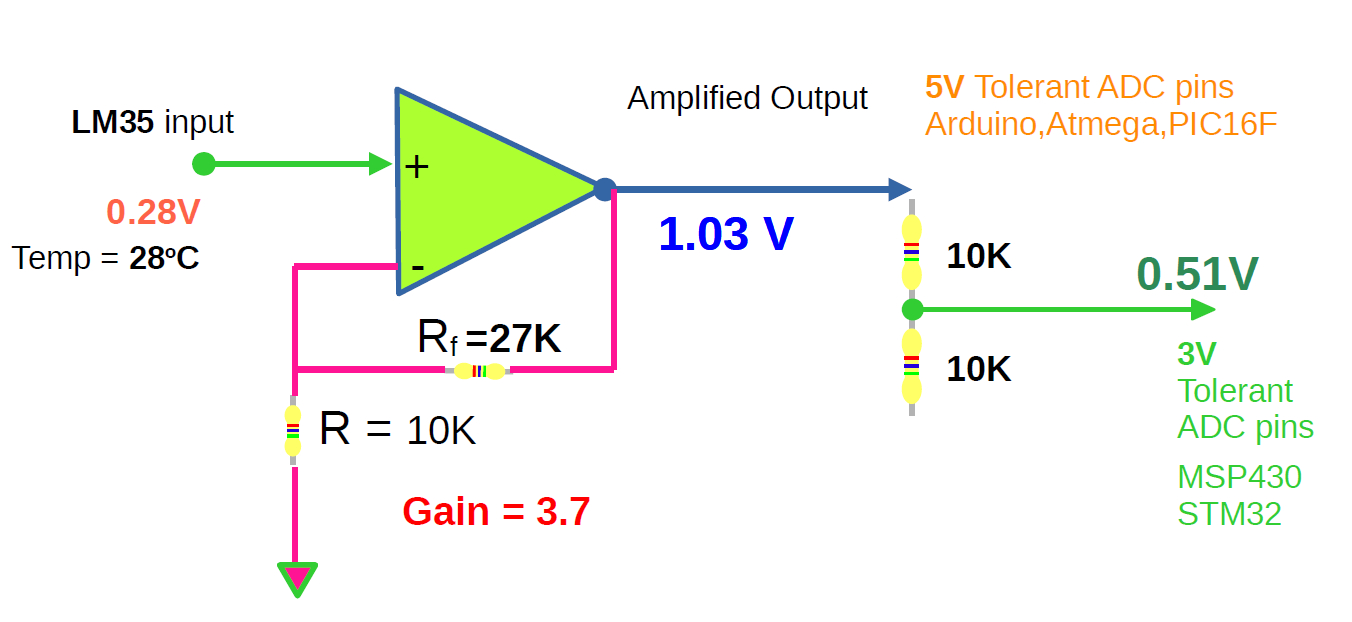
The opamp chosen here is LM324 which has 4 internal amplifiers. Here i will only be showing one of the amplifiers.
The output from the opamp is fed into potential divider which would divide the voltage/2.
The opamp is configured in Non Inverting mode with a gain of 3.7.
Gain(Av) = 1 + Rf/R
Here Rf = 27K and R =10K
so Gain(Av) = 3.7
Main reason gain is chosen as 3.7 is because for the temperature value of 135 degrees the voltage output of opamp will be 5V. This allows to measure almost the whole range of sensor LM35.
Below is a small table of Temperature and corresponding voltage values for gain =3.7 showing the range .
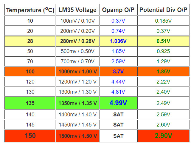
Please note that due to the nature of the analog circuits the gain may vary between each amplifier board due to to the variation in the resistance tolerances.
Another thing to note is that ,LM324 is not a a rail to rail amplifier and cannot swing close to the supply rails.
So the maximum voltage gain is limited to Supply Voltage(V+) - 1.5V So here 5V- 1.5V = 3.5V
So for 5V supply voltage ,you can only measure slightly less than 100C .
You can change it by increasing the supply voltage to a higher value.
The board can handle voltage from 0V to 30V DC.
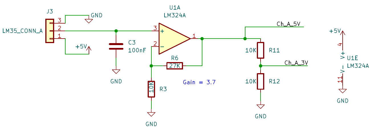
Designing the LM35 Small Signal amplifier using Kicad
In this section we will convert our circuit to a schematic using Kicad 6.0 EDA.You can download the Kicad from here.
The full process is documented in the video given below.
Once you have completed the design of your circuit,Do take a printout of it and manually check it for any errors.
Check this video on how to print your circuit diagram using Kicad
Designing a PCB for 4 Channel LM35 Small Signal amplifier using Kicad 6.0
In this section we will learn to design a PCB for our LM35 amplifier using Kicad 6.0.
The PCB is designed as a double sided board which can be populated with through hole components.
The full design process is available below.
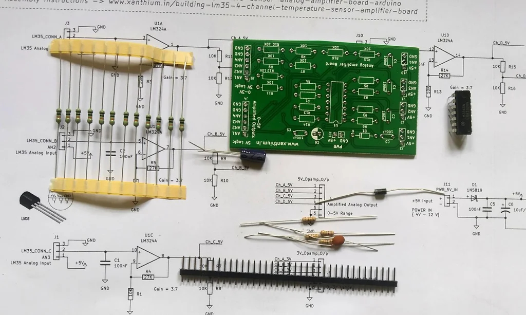
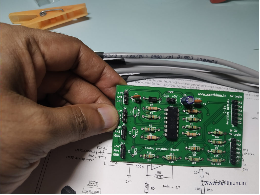
Assembling the LM35 Signal Amplifier board
Here, We will learn how to assemble 4 channel LM35 opamp amplifier KIT.
This DIY KIT will teach you to build your own 4 channel LM35 amplifier for Arduino or other Microcontroller and also help you to improve your soldering and electronics assembly skills .
You can either read the text below or watch the assembly video below.
Required Supplies for the Assembly
- 100nF Ceramic Disc Capacitor
- 10uF/16V Electrolytic Capacitor
- 1N5819 Diode
- 10K Resistor
- 27K Resistor
- LM324A DIP-14
- PCB
- LM35 Shielded Wire
- Heat shrink tubing
- Soldering Iron
Main steps in the assembly are
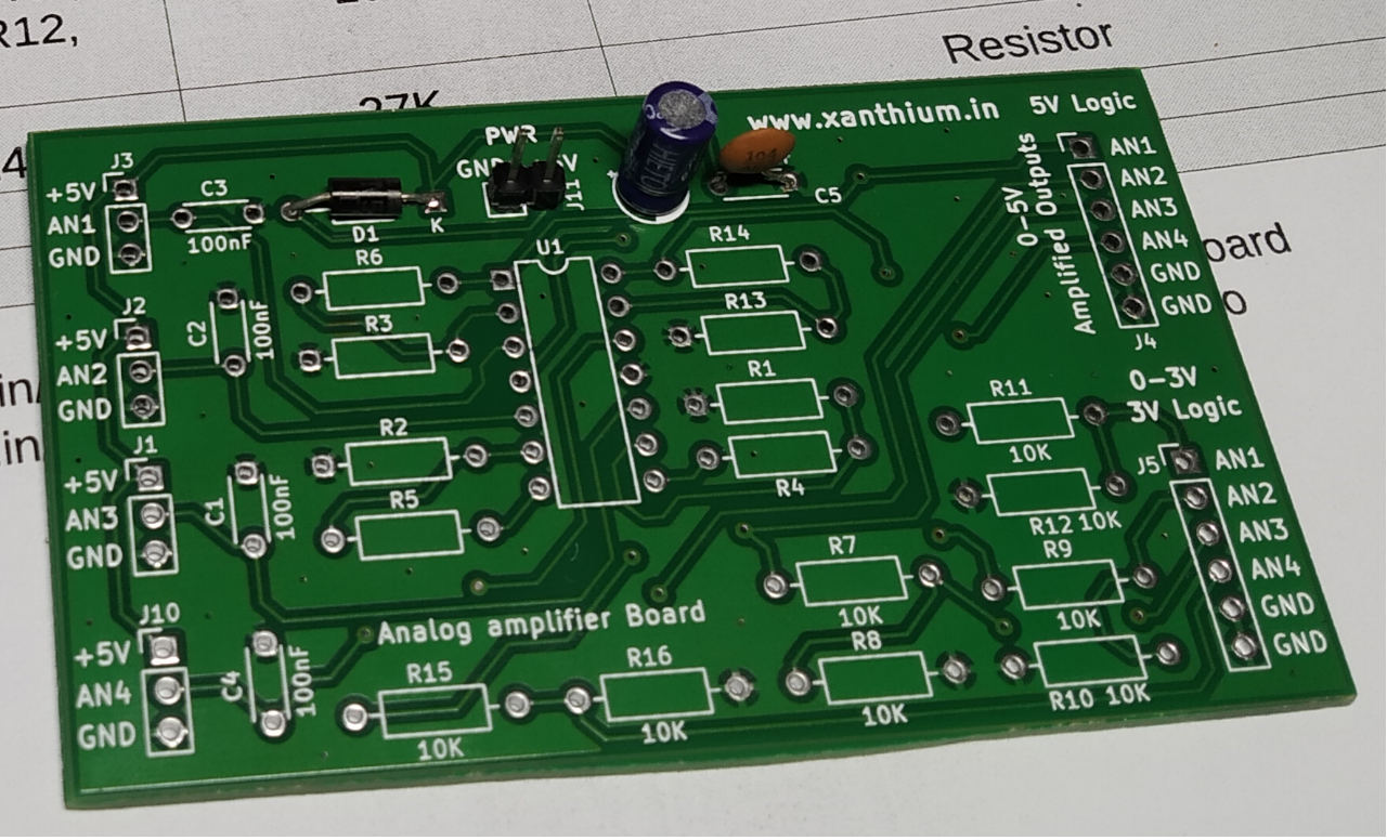
- Clean the PCB with alcohol
- Take the printout of the BOM and Circuit Diagram
BOM and Circuit Diagram can be downloaded from the GitHub Repo.
1)Building the power supply section
First we will build the power supply section consisting of C5,C6 and D1.After the components are soldered ,check whether power supply available through out the board
2) Building the LM324 amplifier section
Here we will solder the LM324 IC for amplifying the signals from LM35 temperature sensor.
The output of the LM35 which will be few 100 millivolts will be amplified to a scale of 0-5V by LM324 opamp IC .This would help to improve the accuracy of the ADC.
This circuit can be used for precision temperature measurement using LM35 and a microcontroller like Arduino,ATmega328P etc.
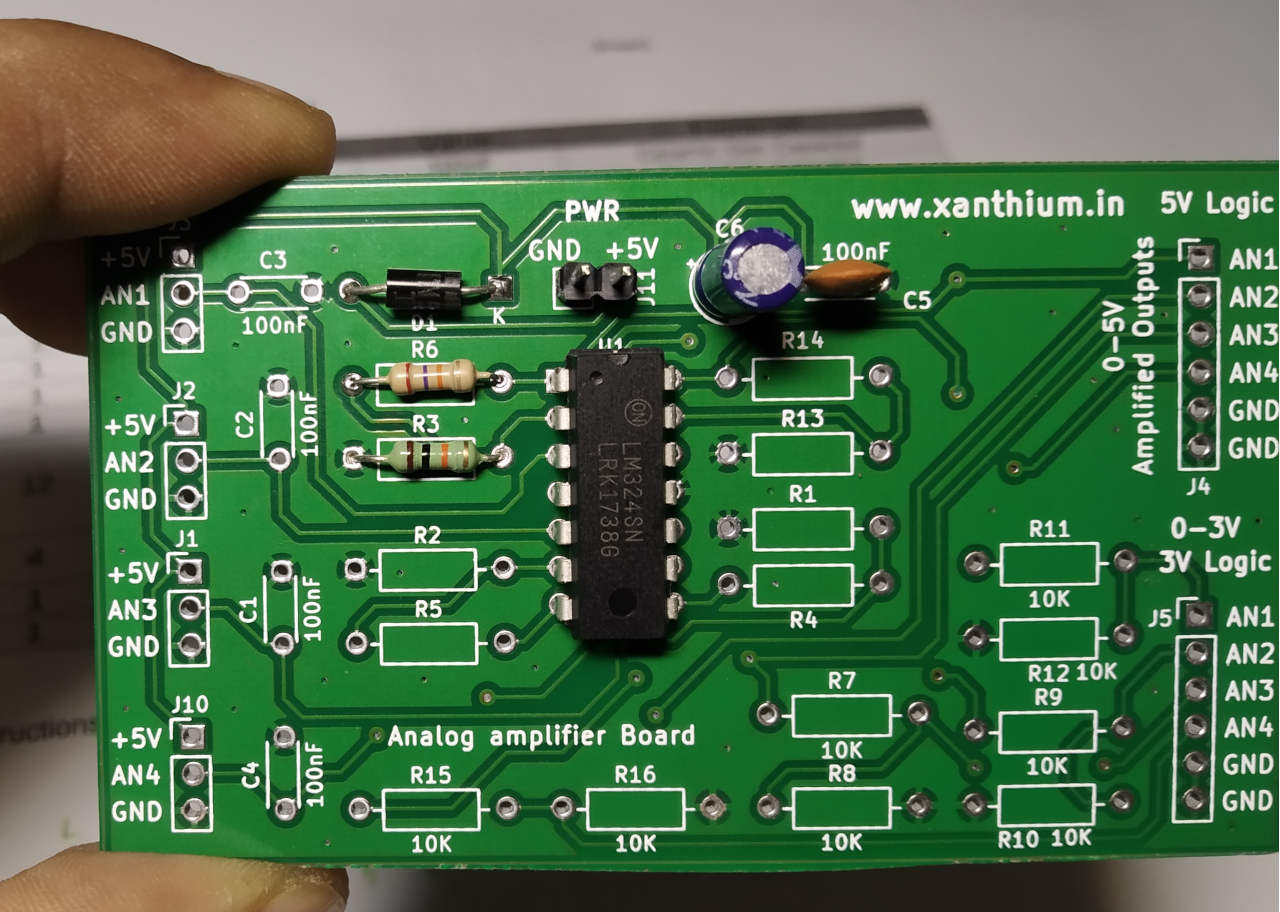
Now we will solder the feedback resistors for setting up the gain of the opamp.
Since the resistance values may vary from what is shown on the resistor color codes, I would recommend you measure the individual resistor values with a multimeter and use it in the gain calculations for more accurate results.
No need to mount the 100nF capacitors C1,C2,C3,C4.
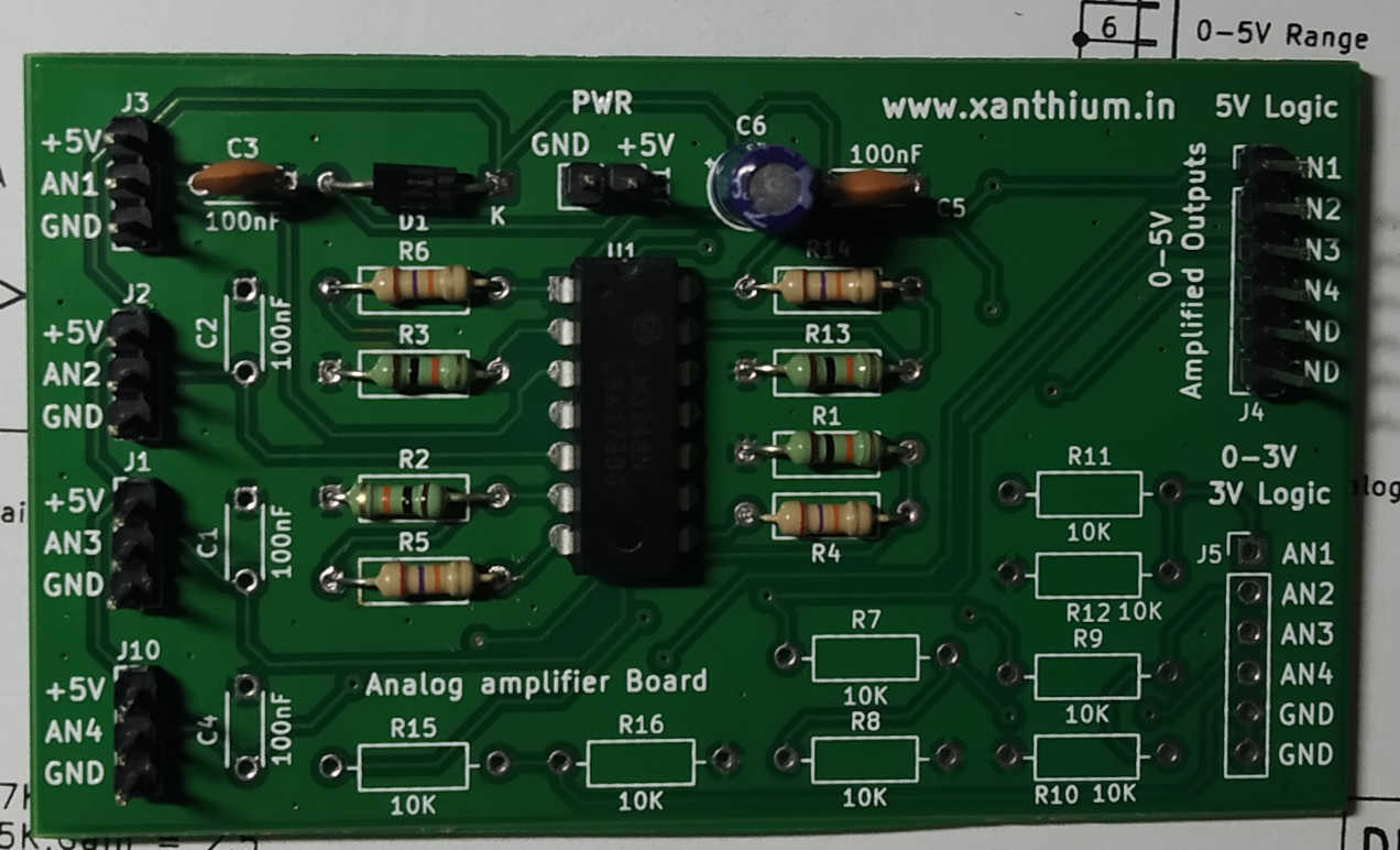
Now we have fully assembled the board along with the voltage dividers for the 3V section as shown in the below image.
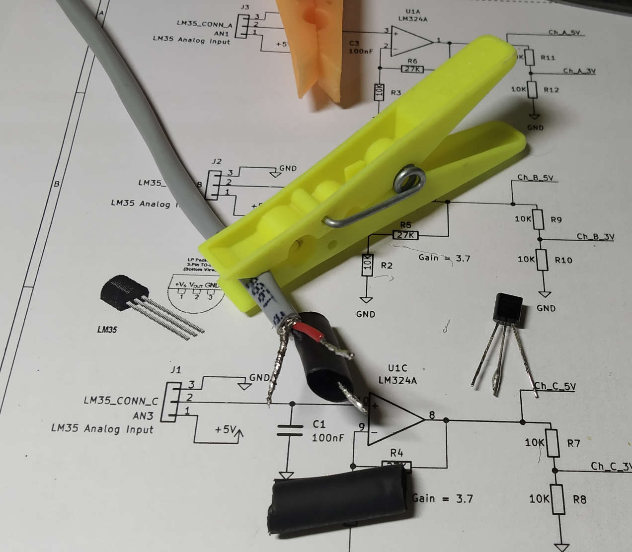
Building the temperature probes using LM35 sensor.
To measure the temperature,
we will enclose our LM35 sensors in the form of a small probe using heat shrink tube so they can be placed at the source of heat.
If you want to monitor the temperature of liquids ,pot the the LM35 sensor in an epoxy to protect from liquid damage or shorting.
The assembly process is shown in the below video.
We will use 2 core shielded wire to connect LM35 to the opamp section.
The shielded wire reduces Noise in the LM35 analog sensor and improves the accuracy of the device.
Please note that the shield of the cable should be connected to ground.
PC temperature Monitoring and Logging using LM35 and Arduino
Now that we have build the four channel LM35 signal conditioning board and the temperature probes, we can interface the LM35 temperature sensors with an Arduino board for monitoring and logging purposes.
The amplifier board helps us to monitor four LM35 analog temperature sensors with the Arduino at the same time.
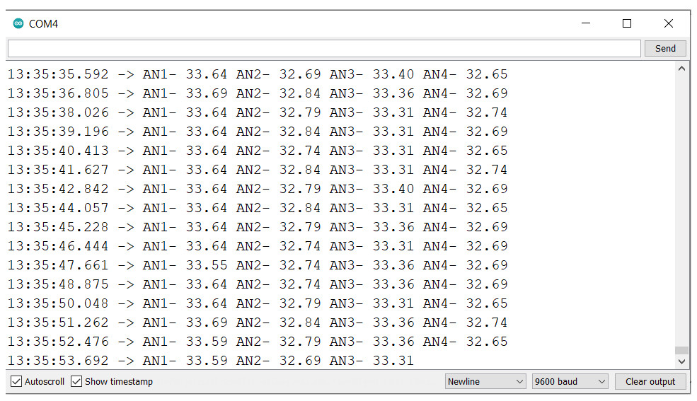
Now we can use the LM35 sensors to monitor the temperature of your PC and log that data to your PC using Arduino IDE .
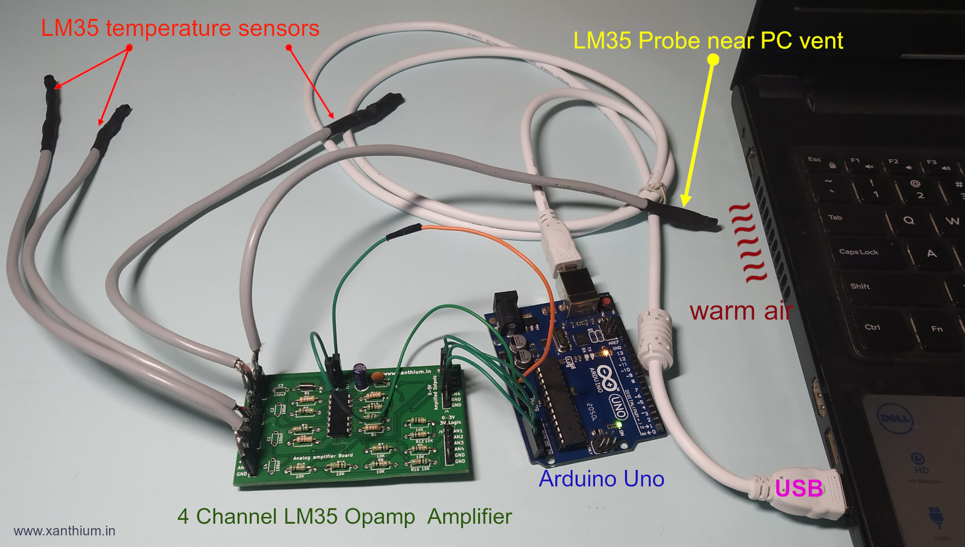
Here we are monitoring the temperature of a PC/Laptop by a LM35 sensor probe placed near the exhaust port of cooling fan.
The temperature of the PC is then compared with ambient temperature.
Here AN1 channel is used to monitor the PC temperature and AN2-AN3-AN4 are used to monitor the ambient temperature.
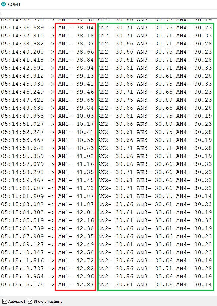
The below image shows the change in temperature as the PC processor is stressed by benchmarking software.
Source codes
Please use the Full code from the Repo.
- Download the PC temperature Monitoring and Logging using LM35 and Arduino code as a Zip file
- Browse the PC temperature Monitoring and Logging using LM35 and Arduino GitHub Repo
Interfacing LM35 Signal Amplifier board with Arduino
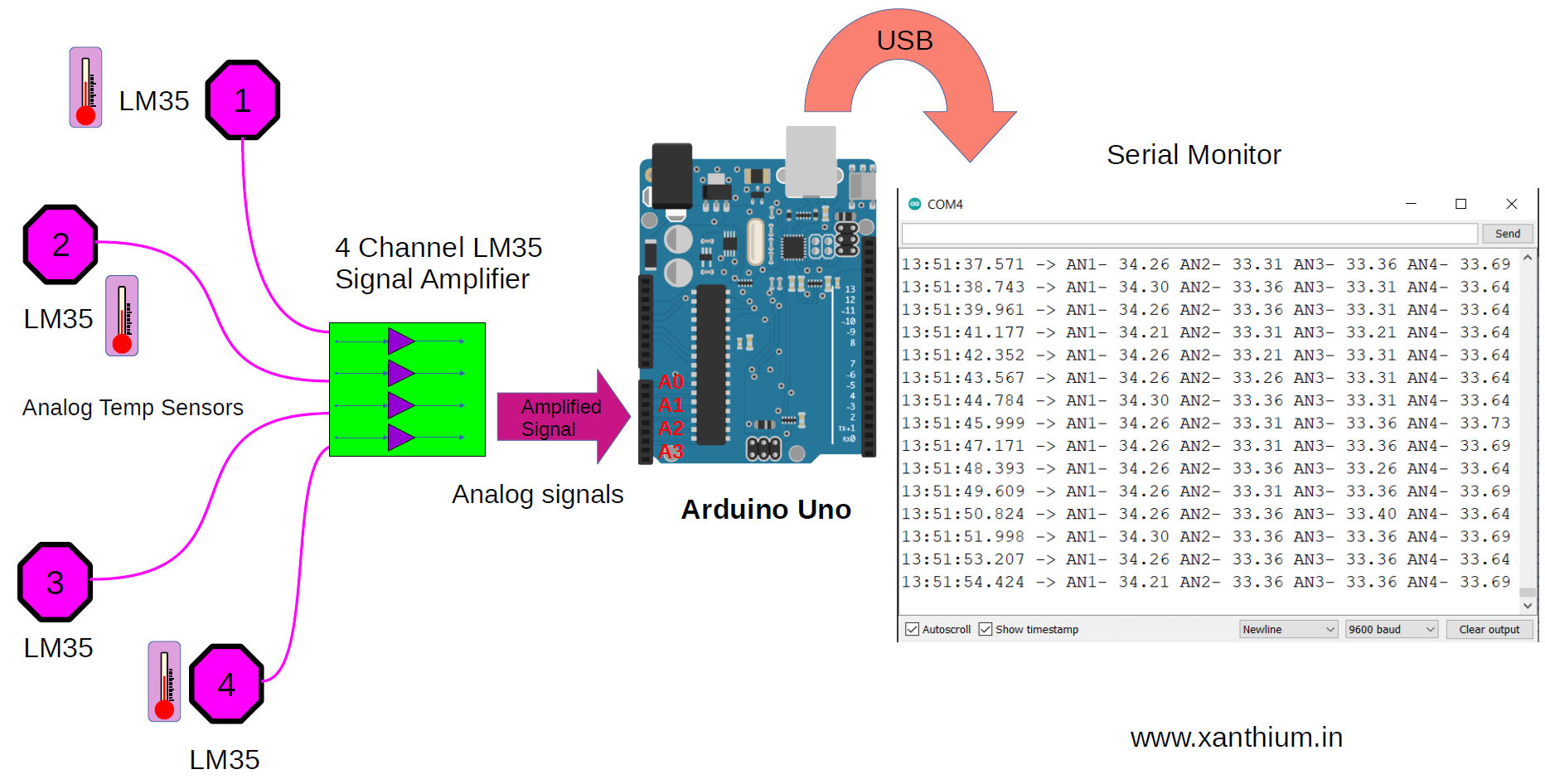
The above figure shows the block diagram of our low cost 4 channel Arduino based DAQ system that can monitor 4 temperature sensors in real time.
The purple octagons numbered from 1 - 4 represents the LM35 temperature sensors that will monitor the temperature and generate voltage corresponding to it (10mV /Degree Celsius).
Calculated Gain vs Actual Gain
The low voltage signals from the LM35 temp sensors are amplified by LM324 opamp which has a gain of 3.4.
The design page of LM324 opamp(above) ,the opamp is designed to have a gain of 3.7 but in the Arduino code we will be using a gain of 3.4.This is because of the tolerances of the resistors used in the circuit.
We have measured the values of the resistors using a multimeter and calculated the actual gain which is only 3.4.
The amplified analog signals are connected to ADC inputs (A0-A4) of Arduino UNO and converted to its corresponding digital values.
The Arduino will convert the analog voltage produced by the 4 LM35 sensors to digital values using the onboard 10 bit ADC .
The digital values are then converted to degree Celsius and then send to a PC using the Arduino serial port. You can then view the data using serial monitor on the Arduino IDE as shown below.
The LM35 sensor produces about 10mV (milli Volt) for every degree increase in temperature ,so for a temperature of 30°C the sensor will produce 300mV( milli Volt).milli volt level signals are prone to noise interference and also by using this range we will not be using the full dynamic range of the ADC.
To utilize the full dynamic range available to us we will adding a signal amplifier before the ADC.
The Signal amplifier is based on the LM324 opamp and will provide a gain of about 3.4.So the input signal will get multiplied by 3.4.
For eg 300mV X 3.4 = 1.02 Volts.Arduino Section
Arduino used in this tutorial is Arduino UNO which has 5 analog Channels and a 10 bit ADC.
The outputs from LM35 signal amplifier is connected to ADC inputs of Arduino from A0 - A4.
The AREF (analog reference) of Arduino is set as default 5V.
5V power for LM35 board is taken from the Arduino board.
Converting LM35 analog values to degree Celsius using Arduino
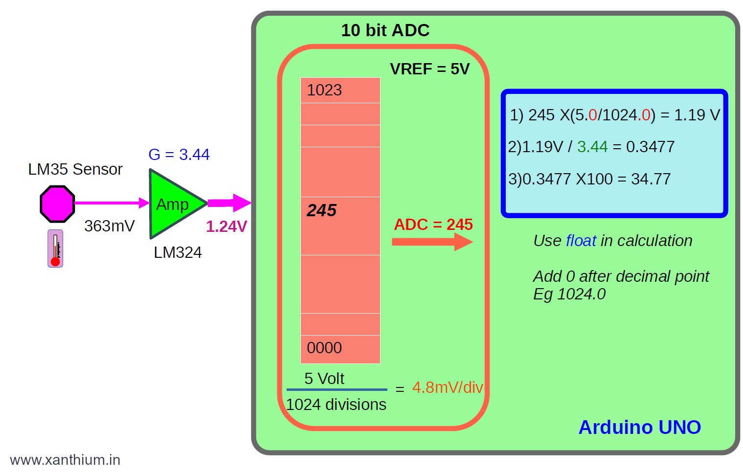
The above image shows the data acquisition process of a single channel Arduino ADC channel and calculations used to to convert the LM35 analog value to digital temperature in degree Celsius.
Explanation of the temperature conversion code
The code for the conversion is shown below.
int AnalogPin_AN1 = A0;    // select the input pin for lm35
float SensorValue_AN1 = 0.0;
void setup()
{
     Serial.begin(9600); //Data will be send to PC
}
void loop()
{
  // Read Analog Value from AN1 pin of the amplifier
  SensorValue_AN1 = analogRead(AnalogPin_AN1);

  // 10 bit adc,1024 divisons,1 div =4.8mV
  // Don't forget to add 0 after decimal point
  SensorValue_AN1 = SensorValue_AN1 * (5.0/1024.0);

  // Dividing by the gain of 3.44,Due to amplifier
  SensorValue_AN1 = SensorValue_AN1/3.44;
  SensorValue_AN1 = SensorValue_AN1 * 100;
  Serial.println( SensorValue_AN1 );
  delay(1000);
}
Here we have an LM35 (purple octagon) producing 363mV which indicates that the temperature is 36.3 °C
The milli volt signal is amplified by the LM324 opamp with a gain of 3.44 to a voltage of 1.24V.
The Voltage 1.24 is fed to the input of Arduino ADC pin (ATmega328P),
Here the ADC is a 10 Bit (210 =1024 divisions) and the analog reference voltage AREF is selected as 5V.
So each ADC step corresponds to 4.8mV (5V/1024 divisions).
For an input of 0V the ADC will give an output of 0000 and for 5V the ADC is give an output of 1023.
For our voltage of 1.24V the ADC will give the output as 245.
SensorValue_AN1 = analogRead(AnalogPin_AN1);Now to get the input Voltage, We multiply the ADC step value 245 with 4.8mV = 1.19V.that is less than the input value of 1.24V.
  // 10 bit adc,1024 divisons,1 div =4.8mV
  // Don't forget to add 0 after decimal point
  SensorValue_AN1 = SensorValue_AN1 * (5.0/1024.0);
To get the Sensor voltage we have to divide 1.24V by the amplification factor of 3.44.The division is there due to the presence of the amplifier.
// Dividing by the gain of 3.44,Due to amplifier
  SensorValue_AN1 = SensorValue_AN1/3.44;
Then you multiply it to adjust the decimal point.
SensorValue_AN1 = SensorValue_AN1 * 100; Precision of the Acquired Data
Here the input temperature is 36.3°C as read by the analog sensor and the temperature calculated by the ADC and Arduino is 34.7°C,So there is an error of 1.6 °C.
If you want to learn, How to save the data coming from a Arduino serial port to a CSV text file or Excel.
- Log in to post comments