
In the ever-evolving landscape of electronic control systems, the need to reliably switch physical devices from a digital command source like a PC or Mac remains a fundamental requirement. USB-controlled relays,or simply "USB relays" provide a straightforward, flexible, and robust interface between computers and electromechanical systems. Whether you're automating a lab experiment, developing a test rig, or deploying a prototype industrial control system, USB relays offer an elegant solution for remote switching, power cycling, and hardware automation.
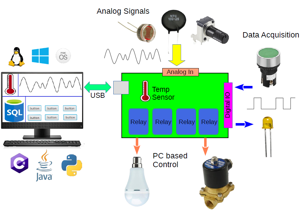
Unlike microcontroller-based relay boards or more complex PLC setups, USB relays are plug-and-play devices that interface directly with a PC or embedded system like Raspberry Pi or Banana Pi via a standard USB port. They combine the reliability of traditional relay hardware with the simplicity of USB communication, making them a powerful tool in the hands of engineers who need to bridge software logic and physical-world control.
In this article, we’ll dive deep into the technical workings of USB relays, explore their applications, and provide practical guidance on integrating them into professional engineering environments
Fundamentals of USB Relay Operation
At their core, USB relays are electrically operated switches controlled via a USB interface. Like traditional relays, they are used to control high-voltage or high-current loads with low-voltage digital signals. However, instead of receiving logic-level input from GPIO pins or control circuits, a USB relay receives commands via the USB protocol typically from a host computer or embedded system.
Most USB relays fall into one of two categories:
Electro Mechanical Relays : Use a physical coil and switch mechanism. They offer excellent isolation and high current handling, but slower switching speeds and limited life cycles (due to mechanical wear).
Solid-State Relays (SSRs): Use semiconductors like TRIACs or MOSFETs to perform switching. They’re faster, silent, and more durable ,ideal for applications requiring high-speed switching or silent operation.
USB Communication Protocols
USB relays can communicate with the host using several protocol types
USB HID (Human Interface Device): Driverless communication, works on most OS platforms without additional drivers.
Virtual COM Port (CDC/ACM): Emulates a serial interface over USB. Easily scriptable using standard serial communication libraries.
Custom Drivers or APIs: Some high-end relays come with vendor-specific SDKs and software libraries for advanced control.
Internally, most USB relay modules feature a microcontroller that interprets USB commands and toggles the appropriate relay channels. Many devices also feature status LEDs, onboard firmware upgradability, and isolation mechanisms between the USB control circuit and the relay drivers.
Key Technical Considerations
When selecting and implementing USB relays in a professional engineering context, understanding the underlying specifications and design trade-offs is critical. This section explores the most important technical factors to evaluate before integrating a USB relay into a system.
Voltage and Current Ratings
The primary role of a relay is to switch electrical loads. Therefore, it's essential to check:
Contact Voltage Rating: This is the maximum voltage the relay contacts can handle (e.g., 30V DC, 250V AC).
Current Rating: Defines the maximum current the contacts can safely carry (commonly 2A to 10A per channel).
Exceeding these ratings can lead to contact arcing, overheating, or failure. Engineers should size relays with at least a 20–30% safety margin, particularly for inductive or capacitive loads.
Number of Channels and Contact Configuration
USB relay modules come in various configurations:
SPST (Single Pole, Single Throw): Basic on/off control for one circuit.
SPDT (Single Pole, Double Throw): Allows switching between two circuits (useful for toggling input sources).
DPDT (Double Pole, Double Throw): Provides more complex switching configurations, often used in industrial logic circuits.
Modules range from 1-channel to 16 or more channels. High-channel-count modules are ideal for test automation or power distribution systems but require careful planning for heat dissipation and cable management.
Electrical Isolation and Protection
A critical design concern is isolating the low-voltage USB control circuit from the high-voltage relay contacts. Look for:
Opto-isolation: Prevents high-voltage transients from reaching the USB port or host system.
Snubber circuits or flyback diodes (for EMRs): Protect the relay driver circuit from inductive spikes when switching motors or solenoids.
ESD protection: Shields the USB data lines from electrostatic discharge.
Failure to properly isolate can result in damaged host computers, data corruption, or even safety hazards.
Switching Speed and Latency
Electro mechanical relays typically operate in the 5–15 ms range.
Solid-state relays can switch in under 1 ms, making them suitable for time-sensitive operations.
In addition to relay switching speed, consider USB command latency and software stack delays, especially if multiple relays must be triggered in a tightly coordinated sequence.
Power Requirements
Bus-Powered Relays: Draw power directly from the USB port (usually up to 500 mA for USB 2.0). Suitable for low-power applications.
Externally Powered Relays: Use an additional power supply to drive the relays. These are more scalable and capable of switching higher loads.
Verify the power budget of your USB host, especially when using hubs or running multiple devices. Excessive draw may cause enumeration failure or unstable operation.
Advantages Over Other Relay Control Methods
In the world of switching and control, USB relays aren’t the only option. Engineers may choose from GPIO-based relays, Ethernet/IP relays, PLCs, or even wireless solutions. However, USB relays offer a unique blend of simplicity, programmability, and flexibility that makes them highly effective in many professional contexts.
Here’s a breakdown of how USB relays compare to other common control methods.
USB Relays vs. GPIO-Controlled Relays
Many engineers working with microcontrollers such as Arduino, STM32, or Raspberry Pi are accustomed to controlling relays via GPIO pins. While this approach works well for embedded applications, it presents limitations in professional and industrial environments.
USB relays are more versatile in terms of host compatibility. They can be controlled from PCs, embedded Linux systems, and single-board computers, making them suitable for both prototyping and production setups. Unlike GPIO relays, which require low-level firmware development, USB relays are easily programmable using high-level languages like Python or C#.
Isolation is another key advantage. Most USB relays include built-in opto-isolators to protect the host system from electrical faults. In contrast, GPIO-controlled relays often require engineers to design custom isolation circuits — increasing complexity and risk.
Deployment is simpler with USB relays. They are typically plug-and-play, requiring no additional hardware design. GPIO-based setups, on the other hand, often demand supporting circuitry, careful power management, and manual configuration.
USB Relays vs. Ethernet Relays
Ethernet-controlled relays are common in industrial systems where distributed control and network-based access are required. However, compared to USB relays, they introduce added complexity and overhead.
USB relays offer low-latency, direct communication between the host and the relay hardware. They require no IP configuration or network infrastructure, making them ideal for local control, test benches, and automation setups. In contrast, Ethernet relays depend on network reliability, and command latency may increase due to TCP/IP stack processing.
Setup and deployment are also simpler with USB relays. They typically work out of the box and don’t require network configuration, firewall adjustments, or security management. Ethernet relays must be assigned IP addresses and are more susceptible to network-related issues or access control concerns.
USB relays are highly portable. They can be moved between systems easily with minimal reconfiguration, which is ideal for labs and mobile test environments. Ethernet relays are better suited for fixed installations in larger facilities, where long-distance control or integration into SCADA systems is required.
In short, USB relays are better suited for local, low-latency control tasks with minimal setup, while Ethernet relays excel in distributed or remote-control applications where networking is a core requirement.
USB Relays vs. PLCs
Programmable Logic Controllers (PLCs) are widely used in industrial automation due to their robustness, long-term reliability, and built-in support for industrial protocols. However, for smaller projects or PC-integrated systems, USB relays can offer a more flexible and cost-effective alternative.
USB relays are significantly less expensive than PLCs and require no specialized hardware or programming environments. They can be controlled using high-level programming languages and integrated directly with PC-based software, making them ideal for test automation, lab control, or small-scale process control.
In contrast, PLCs are typically programmed using ladder logic or proprietary development tools, which can involve a steeper learning curve and longer setup times. While they offer superior durability and I/O scalability, they may be excessive for simpler switching tasks.
USB relays also integrate more naturally with modern computing platforms. They connect directly to Windows, Linux, or macOS systems via USB and are easily controlled through scripting languages or automation software. PLCs often require dedicated interfaces or protocol converters to communicate with a PC or external system.
Software Integration
One of the most compelling advantages of USB relays is their software flexibility. For professional engineers working in automation, test systems, or research, the ability to control relays through code without writing low-level drivers enables rapid integration and customization.
In this section, we’ll explore how USB relays are typically controlled via software, what platforms and languages are commonly supported, and include code examples to demonstrate integration.
USB relays generally fall into one of the following communication models:
HID (Human Interface Device):
Driverless support on Windows, Linux, and macOS.
Recognized as a generic device — communicates using simple read/write commands.
Low-latency and easy to script.
Example use case: Quick Python automation with hidapi.
Virtual COM Port (CDC/ACM):
Appears as a serial (RS-232) interface over USB.
Controlled using standard serial communication libraries.
Simple ASCII command interfaces are common.
Compatible with legacy applications using COM/TTY ports.
Custom USB Protocols with Vendor SDKs:
Some USB relay manufacturers (e.g., Denkovi, Numato, SainSmart) provide DLLs, C libraries, or Python APIs.
Often include features like debounce handling, batch switching, or feedback monitoring.
Engineers should verify which communication model a USB relay supports before purchase, especially if it needs to integrate into existing tool chains.
LabVIEW and MATLAB Integration
Many USB relays can be controlled using LabVIEW via:
VISA serial commands (for COM port devices)
DLL calls (for vendor APIs)
External script invocation
For MATLAB, engineers can use the serialport() or hid interfaces to control relays in experiments or test setups.
Use Cases and Real-World Applications
USB relays are not just lab curiosities or prototyping tools they’re deployed in real-world engineering systems across industries. Their versatility, ease of integration, and cost-efficiency make them attractive in everything from R&D labs to production-line automation.
Below are some of the most relevant professional applications.
Automated Test Equipment (ATE)
In both hardware and firmware validation environments, USB relays play a crucial role in automating test workflows. They are commonly used to switch power to devices under test (DUTs), route signals through different test paths or load banks, and simulate hardware faults such as disconnecting sensors or shorting connections. For example, a company testing embedded controllers might use USB relays to replicate field wiring issues or perform automated power cycling during stress testing — all orchestrated through custom scripts or CI pipelines.Remote Device Power Cycling
USB relays are a practical solution for remotely rebooting unresponsive systems, especially in environments where physical access is limited. Common scenarios include data centers, edge devices in remote locations, or embedded systems deployed as part of continuous integration setups. In firmware development, they are often used to automate power resets during regression testing. Some engineers enhance reliability further by combining USB relays with watchdog timers to automatically reboot systems that stop responding within a predefined window.Industrial Control and Safety Interlocks
While USB relays are not certified for safety-critical applications (e.g., SIL-rated systems), they are widely used for non-critical industrial tasks. These include controlling small machinery, automating lab equipment such as pumps or valves, and switching inputs or outputs in signal conditioning systems. In a chemical lab, for instance, USB relays might control fluid delivery valves with precise timing, all managed from a PC-based control system.IoT Prototyping and Smart Automation Testbeds
USB relays are well-suited for rapid prototyping of IoT and smart home systems. They enable engineers to control physical devices — like appliances, lighting, or actuators — without the overhead of custom PCB design or low-level firmware development. In many testbeds, USB relays are integrated with platforms like Home Assistant or Node-RED, allowing for simulation of smart switches and evaluation of automation logic under real conditions.Academic and Research Laboratories
In scientific research, consistency and automation are essential. USB relays are often used to manage lab instruments, toggle power to sensitive equipment, and coordinate environmental controls such as lighting, fans, or heaters. For example, a physics research team might use USB relays to sequence power supplies and interlocks in a laser experiment, ensuring the setup remains safe and repeatable over time.Other Niche Applications
Beyond mainstream use, USB relays find applications in specialized fields. They’re used to control AV routing in broadcast systems, manage HVAC zones in building simulation environments, and automate power switching during vehicle electronics testing in automotive R&D labs. Their flexibility and ease of integration make them a go-to tool for engineers across a wide range of disciplines.
Common Pitfalls and Best Practices
USB relays are reliable and straightforward to integrate, but in professional settings, improper design choices can introduce bugs, hardware damage, or even safety concerns. Below are the most common pitfalls engineers encounter — and how to avoid them.
Ground Loops and Poor Isolation
Using USB relays without proper electrical isolation between the host system and the switched circuit can lead to ground loops. This often results in intermittent relay behavior, USB communication failures, or even permanent damage to host USB ports.Choose relays with built-in opto-isolation and ensure proper creepage and clearance distances when switching high voltages or inductive loads.Exceeding USB Power Limits
USB 2.0 ports supply a maximum of 500 mA, which can be quickly exceeded when multiple relays are energized or when coils have high inrush current.
Use externally powered USB relay modules for high-current or multi-channel applications, and always verify total current draw during peak switching.Relay Chatter or Misfires
Relay "chatter" rapid, unintended switching can be caused by EMI, unstable power supplies, or race conditions in software. This can damage mechanical contacts or cause system instability.
Best Practice: Implement software-level debouncing and queuing. Use shielded USB cables or USB isolators in electrically noisy environments, and avoid unpowered USB hubs.Device Enumeration Conflicts
In multi-relay setups using identical modules, operating systems may randomly assign different COM ports on reboot, leading to incorrect device mappings.
Best Practice: Use relays with unique serial numbers or identifiers. On Linux, configure persistent device naming using udev rules; on Windows, assign fixed COM ports. Query devices by vendor/product ID if needed.Overstressing Relay Contacts
Driving inductive or high-power loads beyond the relay’s rated capacity shortens its lifespan and can cause contact welding or failure.
Best Practice: Derate relay contacts by at least 20% for inductive loads. Use snubber circuits (for AC) or flyback diodes (for DC) to suppress voltage transients. For high-frequency switching, consider using solid-state relays (SSRs).Poor Software Error Handling
Failing to check for device availability, communication timeouts, or handle disconnections gracefully can lead to software crashes or unpredictable system behavior.
Best Practice: Implement robust exception handling and resource cleanup. Avoid tight polling loops and use event-driven or buffered communication when available.
- Log in to post comments